Get Ad-Free Access: Just $39/year

The 1984 Corvette DIY Guide – Braking

1984 Corvette

The 1984 Corvette DIY Guide – Braking

See full 1984 Corvette Overview and Image Gallery

BRAKES

NOTICE: While Corvsport.com has made every effort to ensure that the instruction provided on this site is both complete and accurate, it is presented here for REFERENCE ONLY.  All vehicle maintenance and repairs should only be performed by a qualified technician or mechanic and should not be attempted without the proper tools and/or experience.  Improperly performed vehicle repair can result in damage, injury, and even death.   User discretion is advised.
CAUTION: When servicing wheel brake parts, do not create dust by grinding or sanding brake linings or by cleaning wheel brake parts with a dry brush or with compressed air.  (A water dampened cloth should be used.)  Many wheel brake parts contain asbestos fibers which can become airborne if dust is created during servicing.  Breathing dust containing asbestos fibers may cause serious bodily harm.
  • Use only D.O.T. 3 or Delco Supreme No. 11 fluid in this brake system.  Do not use silicone brake fluid such as Delcome Supreme No. 24.  Any type of silicone brake fluid may cause seal damage.
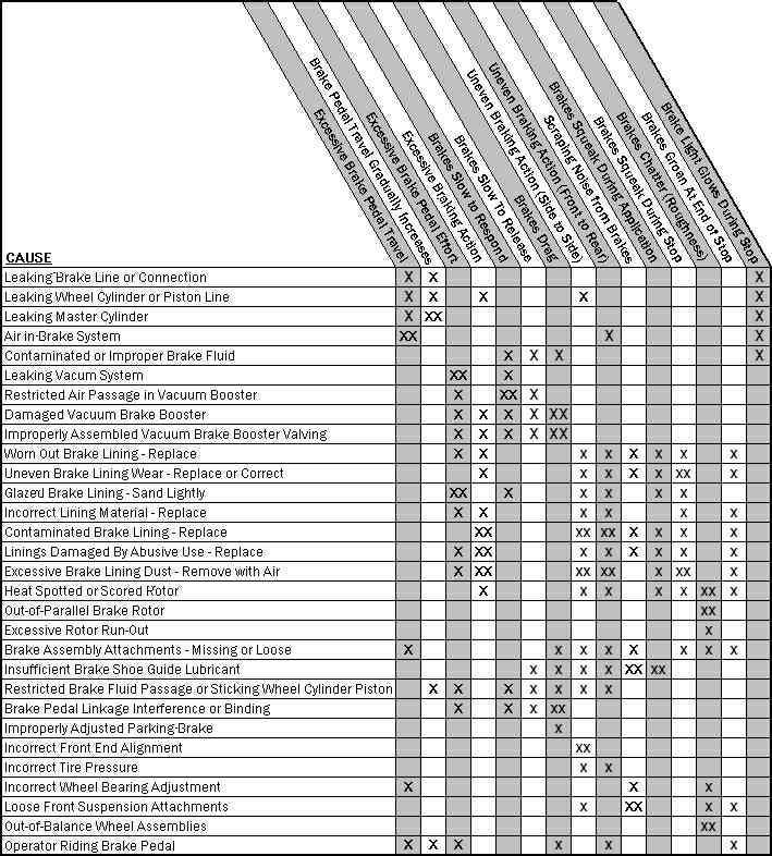
The following diagnosis chart provides probable causes for most mechanical issues involving the braking system.
  • X indicates probable causes
  • XX indicates additional possible causes

PEDAL TRAVEL
At reasonably frequent intervals, the brakes should be inspected for pedal travel, which is the distance the pedal moves toward the floor from a fully released position.  Inspection should be made with the brake pedal firmly depressed approximately 70lbs while brakes are cold.
Pump the pedal a minimum of 3 times with the engine off before making pedal travel checks.  This exhausts the vacuum assist from the power booster.  Pedal travel should not exceed 2.75″ (70mm).
BRAKE PEDAL
Removal
  • Disconnect the battery ground cable.
  • Remove the close out panel and disconnect the courtesy light.
  • Disonnect the brake pedal form the vacuum booster push rod by removing the retainer and washer.
  • Remove the pivot bolt.
  • Remove the brake pedal and all associated mounting parts.
  • To install, follow removal procedures in reverse order. Lubricate bushings, pivot bolt and all friction parts with DelcoBrake Lube (or equivelant.)
  • Adjust the stop lamp switch and check adjustment.
STOP LIGHT SWITCH
Adjustment
The design of the switch and valve mounting provides for automatic adjustment when the brake pedal is manually returned to its mechanical stop as follows:
  • With the brake pedal depressed, insert switch and/or valve assembly into tubular clip until switch body and/or valve assembly seats on tube clip.  Note that audible “clicks” can be heard as threaded portion of switch and valve are pushed through the clip toward the brake pedal.
  • Pull brake pedal fully rearward against pedal stop, until audible “click” sounds can no longer be heard.  Switch and/or valve assembly will be moved in tubular clip providing proper adjustment.(NOTE: Excessive force while adjusting stoplight switch may damage power booster.)
  • Release brake pedal and then repeat the previous step to assure that no audible “click” sounds remain.
BRAKE HOSES
Inspection
The flexible hydraulic brake hose which transmit hydraulic pressure from the steel brake pipe on the frame to the calipers should be inspected every 12 months or 7,500 miles (12,000km).  The brake hose assembly should be checked for road hazard damage, for cracks and chafing of outer cover, and for leaks and blisters.  A light and mirror may be needed for an adequate inspection.  If any of the above conditions are observed on the brake hose, it will be necessary to replace it.
BLEEDING AND FLUSHING BRAKE SYSTEM
A bleeding operation is necessary to remove air whenever it is introduced into the hydraulic brake system.
It may be necessary to bleed the hydraulic system at all four wheels if air has been introduced through low fluid level or by disconnecting brake pipes at the master cylinder.  If the brake piping is disconnected at any wheel, then only that wheel will need to be bled.  If pipes are disconnected at any fitting located between the master cylinder  and wheel, then all wheels served by the disconnected pipe must be bled.
When bleeding the rear brake system, the front of the car should be raised higher than the rear.  This will position the bleeder valve near the 12 o’clock position and prevent air from being trapped in the caliper.
Manual Bleeding
Deplete the vacuum reserve by applying the brake several times.
Bleed the brakes in the following sequence: left rear, right rear, left front and right front.
  • Fill master cylinder with brake fluid and keep at least one-half full of fluid during bleeding operation.
  • With the proper size box end wrench over bleeder valve, attach bleeder tube to valve and allow tube to hang submerged in brake fluid in a clean glass jar.
  • Open the bleeder valve and fully depress the brake pedal.
  • Close bleeder valve and release brake pedal.
  • Repeat previous two steps until all the air is evacuated.  Check and refill master cylinder reservoir as required to prevent air from being drawn through the master cylinder.
  • Repeat the bleeding procedure at all wheels if the entire system is to be bled.
  • Check the brake pedal feel for “sponginess” and repeat entire bleeding procedure if necessary.
FLUSHING BRAKE HYDRAULIC SYSTEM
It is recommended that the entire hydraulic system be thoroughly flushed with clean brake fluid whenever new parts are installed in the hydraulic system.  Flushing is also recommended if there is any doubt as to the grade of fluid in the system.  If fluid has been used which contains the slightest trace of mineral oil, all rubber parts that have been exposed to the contaminated fluid should be replaced.
PARKING BRAKE ADJUSTMENT
  • Raise the vehicle and remove the rear wheels, replace two wheel lug nuts opposite of each other on rotor to insure correct disc/drum position.
  • Back the caliper piston into its bore.
  • Loosen the park brake cable so that there is no tension on the park brake shoes.
  • Rotate the disc so that the hole in the disc/drum face will align with the star adjuster.
  • To make the adjustment, insert a flat blade screwdriver through the hole in the disc face.
  • For the driver’s side: Move the handle of the tool towards the ceiling to adjust the shoes out and towards the floor to adjust the shoe out and towards the floor to adjust the shoes in.
  • For the passenger’s side: Move the handle of the tool towards the floor to adjust the shoes out and towards the ceiling to adjust them in.
  • Adjust one side at a time until there is no rotation of the disc/drum.  Then back the star adjuster off 5 to 7 notches.  Proceed to do the same on the opposite side.
  • Replace rear wheels.
  • Apply the park brake lever two notches.
  • Adjust the cable at the equalizer so that the wheel has drag.
  • Release the park brake lever and check the wheel for free rotation.
  • Correct adjustment will result in no drag on the wheel.
ROTOR SERVICING AND CHECKING PROCEDURE
Front
Raise vehicle on hoist or other methods that do not involve lifting the vehicle by the wheels.  Remove wheel assembly and replace two lug nuts to ensure proper disc alignment.  Clamp a dial indicator to the caliper so that its button contacts the disc at a point about 1/2 inch from the outer edge.  When the disc is turned, the indicator reading should not exceed .006″.  If runout exceeds this amount, the hub and disc assembly should be repaired (turned) or replaced.
Rear
Dial indicate the disc face.  If lateral runout of the disc exceeds the bearing end play by .006″ (.15mm), the disc should be repaired (turned) or replaced.
DISC MACHINING
The condition of the disc is a vital factor in the efficient functioning of the brake.
The disc should run true between the pads.  The maximum run-out permissible is .006″ (0.15mm) and if this tolerance is exceeded, it may cause pedal flutter or increased pedal travel.  It is also essential that parallelism is maintained at less than .0005″ (0.013mm).  The surface of the disc should be smooth.  The scratches and light scoring which appear after normal use are not detrimental to operation, but a heavily scored disc will impair efficiency and increase pad wear.
If the disc run-out exceeds .006″ (0.15mm) or is heavily scored, it is permissible to machine the disc but the thickness of the disc must not, under any circumstances, be reduced below the minimum recommended figure of 18.4mm (0.724″).  the minimum disc thickness must be obtained by removing equal amounts from both disc faces.  Under no circumstances should the maximum machining allowance be taken from only one face.  In cases where the disc does not clean up within these tolerances, a new disc must be fitted.
ROTOR THICKNESS
  • Minimum Disc Thickness – 5.0mm per disc.
  • Minimum Thickness after refinishing – 18.44mm (.724″)
MASTER CYLINDER ASSEMBLY
The master cylinder assembly is an aluminum-plastic composite, featuring an integral proportioning valve/warning switch.  The cylinder has dual pressure chambers with a primary piston to supply hydraulic pressure to the rear brakes and a secondary piston to pressurize the front brakes.  The cylinder is designed for a conventional front/rear split brake system with one outlet for both front brakes and one outlet for both rear brakes.  The master cylinder has one reservoir mounted over, and supplying fluid directly to, the primary pressure chamber.  However, the reservoir is also connected to an adapter elbow to supply fluid to the secondary pressure chamber.
REMOVE AND INSTALL MASTER CYLINDER ASSEMBLY
Remove
  • Loosen tube nuts and disconnect two hydraulic brake pipes.  
  • Plug pipes to prevent entrance of contaminates.
  • Remove attaching nuts.
  • Remove Master Cylinder Assembly.
Install
  • Install master cylinder (as shown.)
  • Torque attaching nuts to 20-34 N-m (15-25 lb-ft).
  • Attach tube nuts and torque to 16-20 N-m (12-15 lb-ft).
REMOVE AND INSTALL BRAKE PADS
Remove
  • Remove 2/3 of the brake fluid from the master cylinder reservoirs.
  • Hoist and support vehicle.  Mark relationship of wheel to axle.  Remove wheel.  Inspect rotor – if machining is necessary refer to removal procedures later in this section.  Install two lug nuts to hold rotor in position.
  • Position a C-clamp as shown and tighten until piston bottoms in bore. Make sure one end of C-clamp rests of inlet fitting bolt head and the other against the outboard shoe.
  • Remove and discard the upper caliper self-locking bolt, and rotate caliper about the lower bolt and guide pin to expose shoe and lining assemblies.
  • Remove shoe and lining assemblies.
  • Remove all residue from pad abutments on mounting bracket and from the inside of the housing outer legs.
  • Check guide pins for free movement in bracket.  Replace guide pins or guide pin boots if corroded or deteriorated.
Install
  • Install new pad and lining assemblies on mounting bracket.  NOTE: Shoe and lining with insulator is installed outboard. Wear sensors must be in trailing position with forward wheel rotation.  If not, use the other inboard pad and lining in the replacement set.
  • Rotate caliper back into the operating position.  Inspect the shoe springs.  If they are protruding through the inspection hole, rotate the caliper and readjust.
  • Install a new self locking bolt and torque to 30-34 N-m (22-25 lb-ft.)
  • Properly install wheel and lower vehicle.
  • Fill master cylinder to proper level.  Bleed brakes if inlet fitting was removed.
  • Pump brake pedal firmly and slowly three times to bring pads into contact with rotor.
  • Fill reservoirs to proper level.
  • Road test the vehicle.
PARKING BRAKE ASSEMBLY
General Description
The parking brake assembly operates on the Duo Servo principle, where the primary shoe is forced against the drum by application of the parking brake handle.  Force from the primary shoe is then transferred to the secondary shoe and multiplied by a wrapping action caused by drum rotation.  Stainless steel wear strips are attached to the aluminum housing to prevent premature or excessive wear.  All springs are stainless steel and other attaching components are plated.
CAUTION: When servicing wheel brake parts, do not create dust by grinding or sanding brake linings or be cleaning wheel brake parts with compressed air.  (A water dampened cloth should be used.)  Some wheel brake parts contain asbestos fibers which can become airborne if dust is created during servicing.  Breathing dust containing asbestos fibers may cause serious bodily harm.
REMOVE AND INSTALL PARKING BRAKE COMPONENTS
NOTICE: Be careful not to damage wear shims.  If damaged, it will be necessary to replace the entire mounting plate assembly.
Remove
  • Spread shoes and remove adjuster assembly.
  • Remove the adjuster return spring.
  • Disengage the hold down springs and pins by pushing down on the spring and then sliding the pin until it can be removed through the hole at the end of the slot.  Remove pins and springs from shoes.
  • Remove the shoe return spring with a suitable pair of pliers.
  • Remove the primary and secondary shoe and lining assemblies.
  • Disassemble adjuster assembly and inspect threads for wear, burrs or damage.  Replace as necessary.
  • Clean and inspect wear bracket and wear shims for burrs or damage.  If the shims or bracket are unserviceable then it will be necessary to replace the mounting plate assembly.
  • Inspect the rubber boot around the lever strut assembly.  Install a new rubber boot if the old boot is cracked or torn.
  • Inspect springs for wear or damage and replace as necessary.
Install
  • Clean all parts, excluding shoe and lining assemblies not being replaced in clean denatured alcohol.  Lube wear brackets and wear shims with a thin coating of GM Part No. 5450032 -Delco Brake Lube (or equivalent.)
  • Fit shoe and linings to mounting plate.  Primary and secondary shoe and assemblies are identical. NOTE: Make sure operating lever and strut assembly is positioned on the wear shims, not down in the hole.
  • Install shoe return springs with suitable pliers.
  • Install pins and hold down springs by fitting to shoe and then depressing the spring to extend the pin head through the hole in the backing plate and then down into the slot.
  • Install the adjuster return spring.
  • Install the adjuster assembly, making sure the star wheel is positioned properly, star wheel toward front.
  • Adjust shoe and lining assemblies and cable after installing rotor and caliper per parking brake adjuster procedure.