

1967 Corvette Overview – The Ultimate Guide
There were varying reports as to why General Motors decided to keep the current model around for one more year. Some speculated that the launch of the C3 was intentionally delayed because Chevrolet had introduced the Camaro to its lineup in 1967. Although many critics and enthusiasts proclaimed that the 1967 Corvette Sting Ray would in fact be the first of an entirely new generation of Corvettes, it turned out that it would actually be the last – and most refined of the C2’s.
Factually, however, most of it stemmed from the large levels of apprehension about Corvette’s successor, especially centered around issues with undesirable aerodynamics. Zora Arkus-Duntov, who had been directly involved with the development of the second-generation Corvette and was now championing the third-gen, had demanded that more time in the wind tunnel be given to the new Corvette prototype.
The early results of such testing on the prospective third-generation model had proven that the car had undesirable aerodynamics, an issue Duntov had hoped to clear up well before the new Corvette went into production.
Not surprisingly, the 1967 Corvette proved to be the most sophisticated of all the Sting Ray models. The second-generation Sting Ray had been refined to its evolutionary limits – the result of which was a car that was clearly the best model of its five-year run.
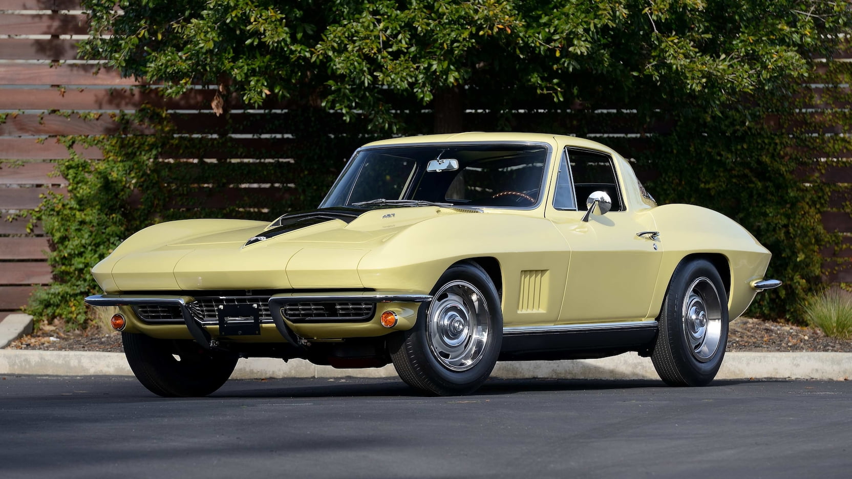
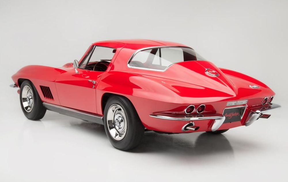
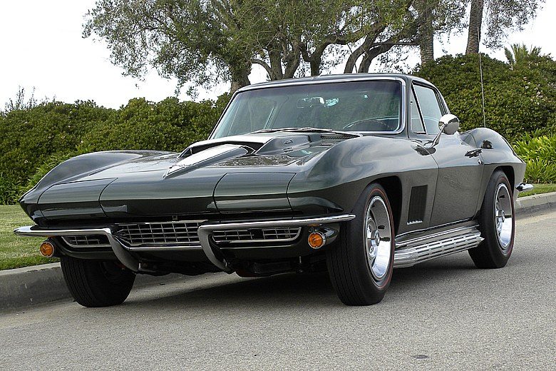
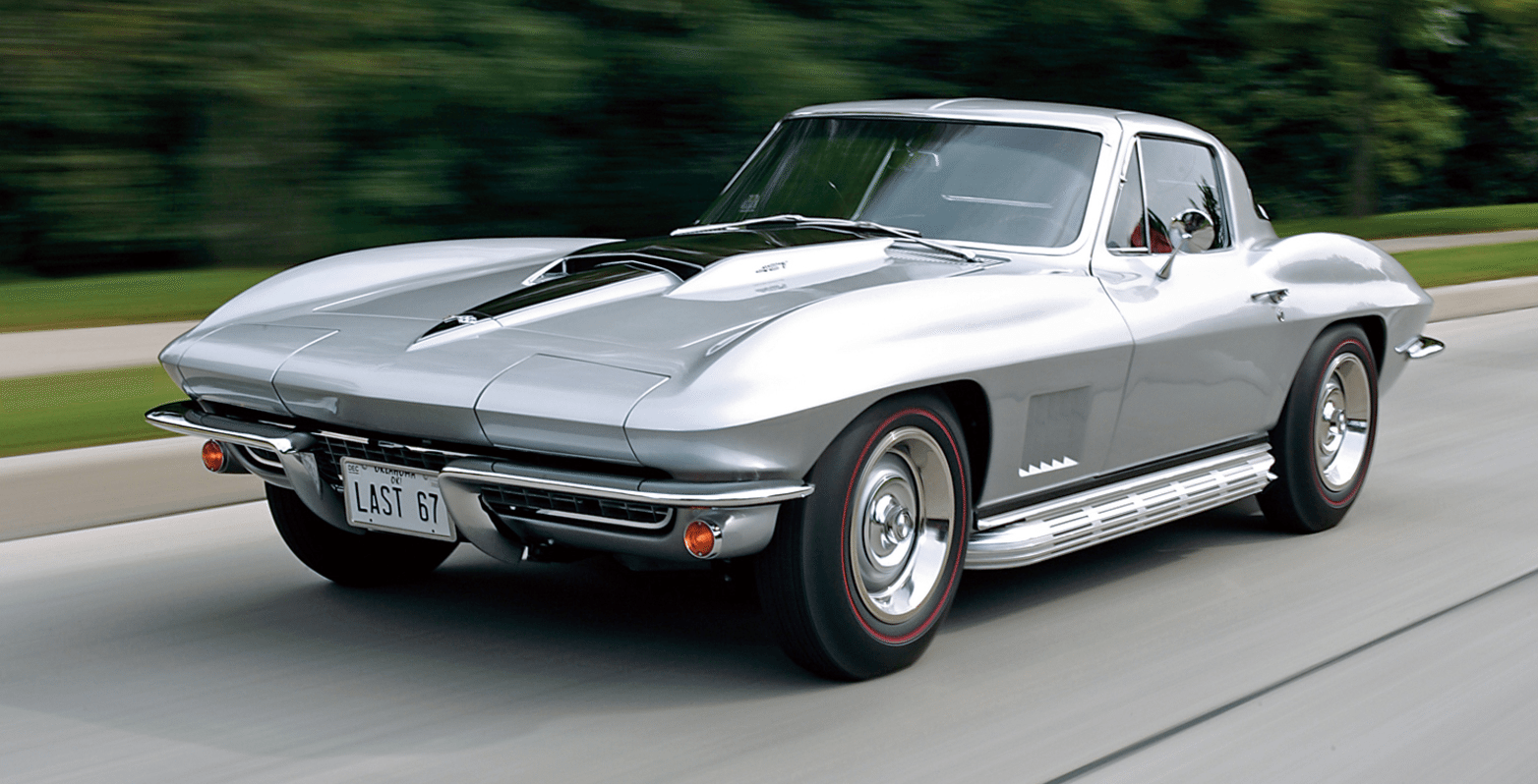
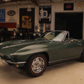
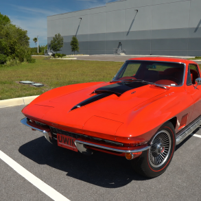
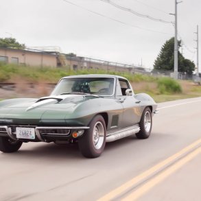
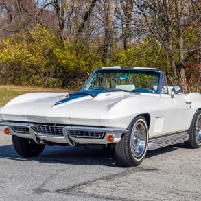
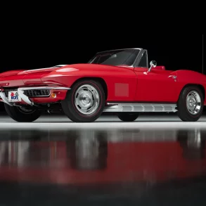
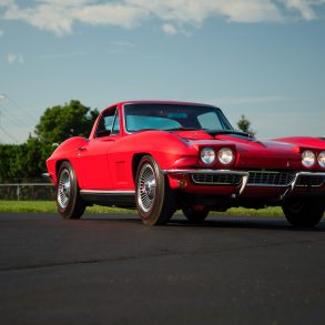
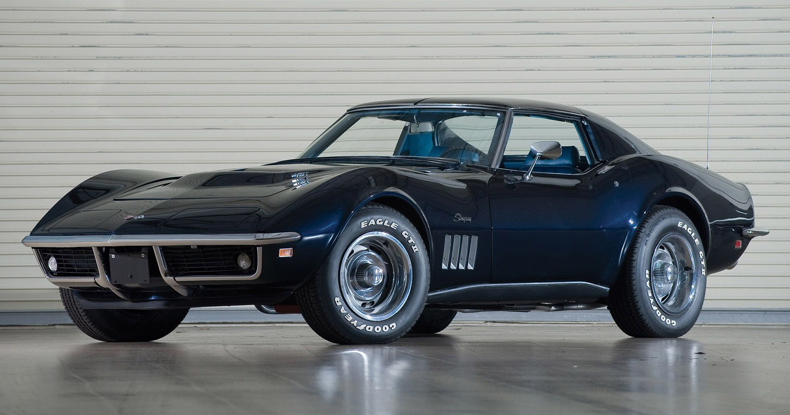
The ‘67’s lines were the cleanest of all the C2’s, though the changes that were made to the Corvette were modest (just as they had been on the 1966 model.) To start, much of the trim (including hood script emblems and fender flags) were removed. The front fenders now featured five smaller air vents in place of the three larger ones that had originally been introduced in 1965.
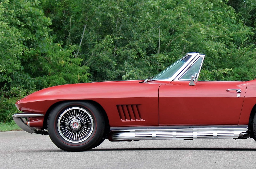
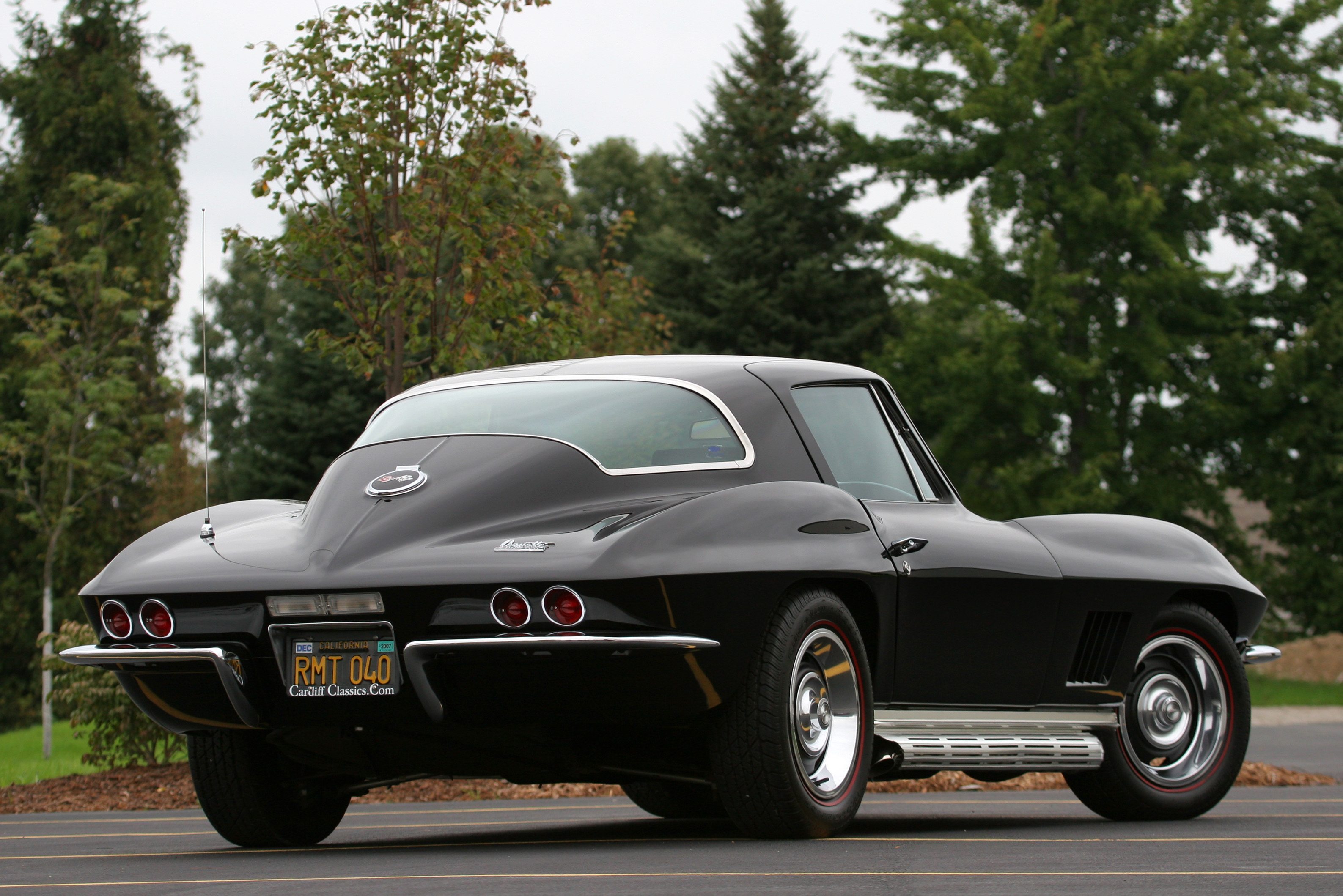
The rocker panels were given a flat finish without any ribbing, which gave the car a lower, smoother outward appearance. In the rear of the car, a new, single backup light was introduced (unique only to the 1967 model) over the license plate. Lastly, the earlier models’ wheel covers were replaced with slotted six-inch Rally wheels with chrome beauty rings and lug nuts that were concealed behind small chrome caps.
In truth, the change of wheels was as much a result of safety legislation which required modifying the use of a knock-off wheel to a bolt-on type.
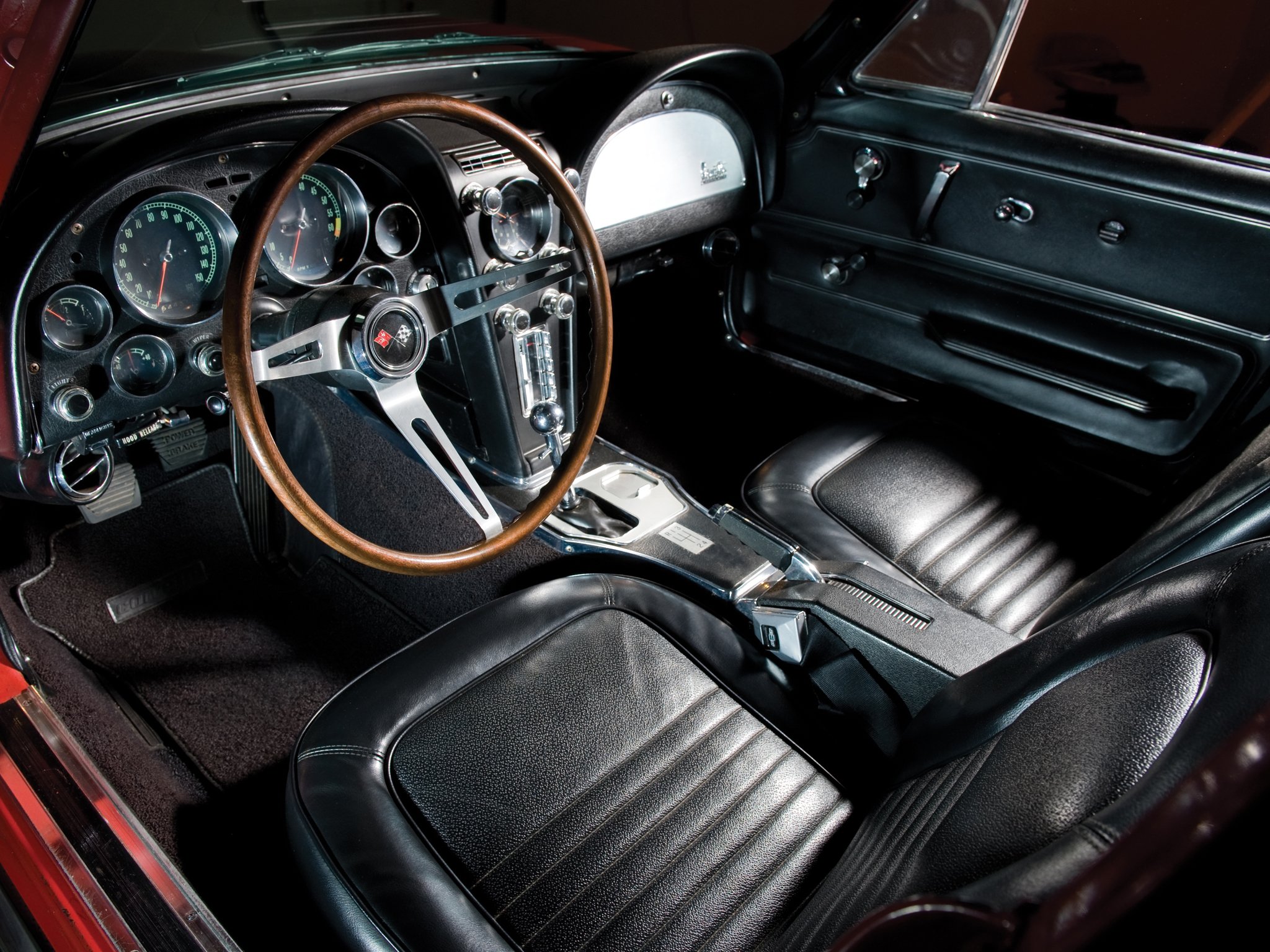
Also like the 1966 model, the 1967 only received minor updates to its interior. As with before, the upholstery was revised and the seats were a new design. The hand brake (parking brake) was relocated from beneath the dashboard to between the seats – a Corvette first. While the inner doors remained largely the same as before, the lock buttons were moved further forward and an attaching screw was added at the rear. Perhaps the most notable change to the 1967 Corvette’s interior was the removal of the passenger hand-hold above the glovebox, a feature that had been part of the Corvette since 1958.
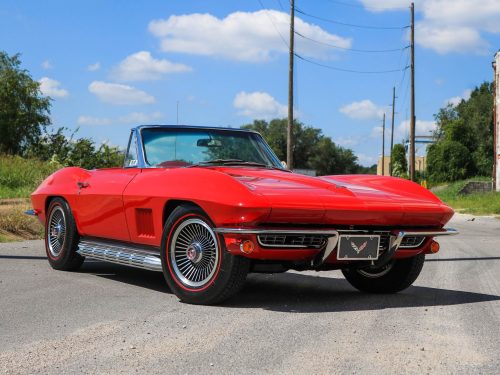
The convertible’s optional hardtop offered with a black vinyl cover, which had been a fad among the automotive industry as a whole during that time.
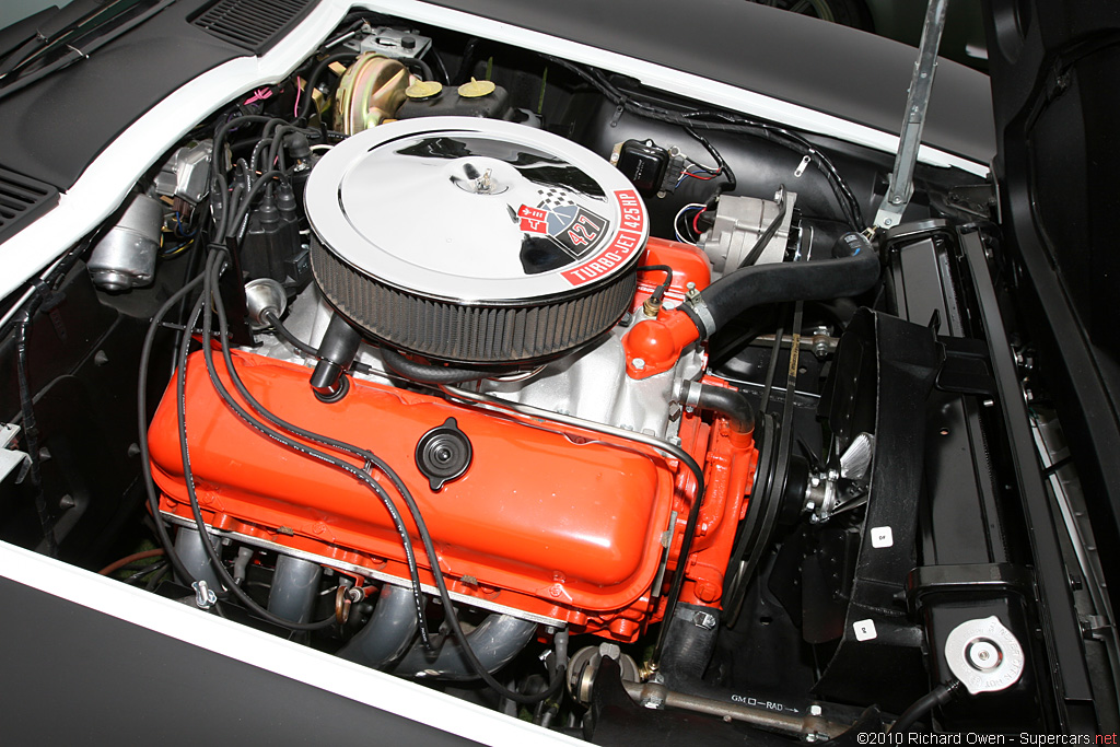
Even fewer changes were made to the ‘67’s powertrain. As with the previous year, the two small-block V-8 engines returned, as did the 390 horsepower big-block, though this last engine was fitted under a redesigned hood scoop.
The biggest changes involved the pair of big-block 427 engines, which now produced 400 and 435 brake horsepower respectively, due to the introduction of triple two-barrel carburetors. Like last year’s model, these new 427s differed in compression ratios – 10.25:1 and 11.0:1 respectively. The latter of these two engines, RPO L71, also included optional specialized aluminum heads (instead of cast iron) and larger-diameter exhaust valves like those included in RPO L89. Also as with previous years, the actual (true) horsepower of these behemoths was largely understated.
DID YOU KNOW: While there are many unique identifiers that single out any model year of Corvette, the 1967 Sting Ray has a unique identifier to help set it apart – If you know where to look. A blue, “GM Mark of Excellence” label was attached to the back of each 1967 Corvette door above the latch. This initiative was the direct result of General Motor’s quality awareness program. Additionally, safety legislation required a modification of the knock off wheel option. For the 1967 model year, the wheels were changed to a bolt on, cast alloy style with a clip on center cap to conceal the lug nuts.
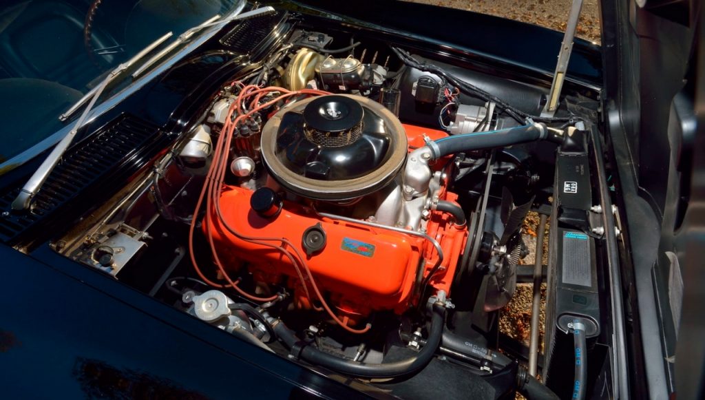
Based on the already impressive L89 engine, Chevrolet decided to introduce the “ultimate” Corvette engine in 1967 by introducing an engine coded with the designation L88. The L88 engine was an immensely powerful production engine, and was about as close to a pure racing engine as any Chevrolet had introduced in a commercial vehicle up to that point in time.
The big-block engine featured weight-saving aluminum cylinder heads mounted atop a standard Mark IV four-bolt iron block. The L88’s crankshaft was specially forged out of 5140 alloy steel, and was then cross-drilled for maximum lubrication and Tuftrided for hardness. Attached to the crankshaft via Magnafluxed connecting rods were eight forged-aluminum pop-up pistons that produced an air/fuel mixture at a staggering 12.5:1 compression ratio.
Although General Motors claimed that it was no longer involved with racing (due to their commitment to support the Automobile Manufacturers Association’s ban on racing), there was no question that all twenty of these special L88 engines were intended for the racetrack.
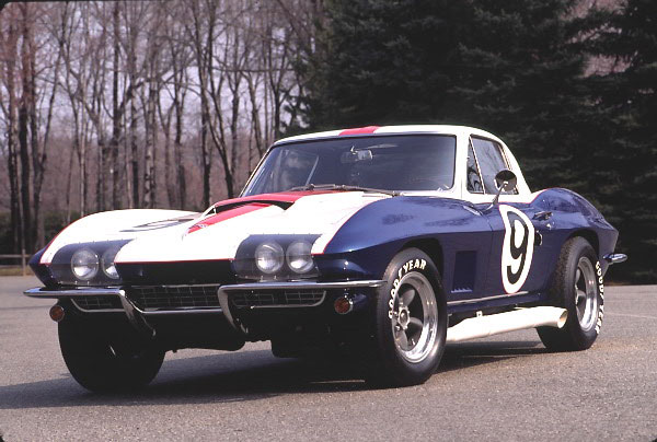
The L88 was yet another of Zora Arkus-Duntov’s unabashed attempts at elevating the Corvette to the stature of a race car, which is where he knew the Sting Ray ultimately belonged. However, when the engine was originally introduced to Corvette in the spring of 1967, the engine didn’t light the racing circuits afire as the L88 had durability problems early on in its career.
The engine was prone to overheating and utilized underrated (and inherently weak) connecting rods in the engine’s lower end. Nonetheless, the 1967 L88 equipped Corvette was definitely worth taking notice of, and proved that it had mastered the ability to go fast . At the 24 Hours of LeMans in June, 1967, a Corvette equipped with an L88 actually topped 170 miles per hour on the Mulsanne Straight before a connecting rod failed, thereby ending Corvette’s chance for a victory at the 24 hour race.
Of course, ordering the L88 production option meant more than just placing an order for an engine. When equipped with the L88 427 Corvette engine, the build also called for blank covers to replace both the AM/FM radio controls and the heating/cooling controls normally found in the center console of a ’67 Corvette’s dashboard. In fact, ordering the big-block 427 also meant the mandatory elimination of a radio head and power windows, as well as the elimination of a convenient automatic engine choke – though Chevrolet did have a retrofit hand-choke kit available for those drivers that could not get along without it.
In addition to the removal of some of the car’s creature comforts, other notable absences could be found under the hood. First, the fan shroud (which aids in engine cooling) was absent, as was any semblance of an emissions controls system. There was no PCV (Positive Crankcase Ventilation) valve, but rather an obsolete road-draft tube that vented crankcase vapors directly into the atmosphere through the driver’s side valve cover. What was left instead was an impressive engine that was as perfectly suited to run on the racetrack.
If ever an off-road engine option had been developed for the Corvette, this was it. The L88’s ultra-high compression ratio left Chevrolet officials no choice but to warn owners about the car’s fuel consumption. The paperwork that was included with each Corvette equipped with the L88 option read “This unit operates on Sunoco 260 or equivalent gas of very high octane. Under no circumstances should regular gasoline be used.” A second label was placed inside the Corvette as well which similarly read “Warning: Vehicle must operate on a fuel having a minimum of 103 research octane and 95 motor octane or engine damage may result.”
Ultimately, sales of the L88 equipped Corvette were limited to a mere 20 units. While the car was immensely powerful, it was also an extremely expensive option. At an additional $1,500 over the base price of $4,240.75, the sticker shock proved too expensive for most enthusiasts, which was okay with GM since they had always felt that the L88 Corvette belonged on the racetrack.
Production Volumes
As a whole, sales of the 1967 Corvette Sting Ray were down from earlier models. GM attributed most of the sales lag as a bi-product of the anticipated arrival of Corvette’s overdue redesign. With a third-generation Corvette just around the corner, the final year of the C2 Corvette still produced respectable sales numbers. In total, 22,940 units were sold, which was down over 5,000 units from the 1966 sales numbers, with the convertible accounting for nearly two-thirds of all sales with an impressive 14,436 units sold to the coupes meager 8,504 units.
Even as the sales numbers began to reach an end for the C2 Corvette, Chevrolet was ramping up for the introduction of its next-generation Corvette. While the introduction of the C3 Corvette would include the discontinuation of the Sting Ray designation (an absence that was more than five years in the making,) the new Corvette would continue to retain a marine-based designation, though this time as a nickname. As 1968 approached, General Motors was about to unveil the “Shark”, and its unveiling would usher in another challenging era for both the Corvette and late-1960’s America.
1967 Corvette Specifications & Performance
See the complete breakdown of technical specifications for the 1967 Corvette, including engine, suspension, brakes, body dimensions, and power. Read more: 1967 Corvette Specifications.
Engine & Transmission
Quite a few modifications to the visual look and performance of the 1967 modelscausede many critics to deem the 1967 model the best of the second-generation Corvettes. The major modifications to the engineweres the 427 V8s switch to the three 2-barrel carburetors, which increased horsepower to 400 and 435 depending on which version was chosen (the latter was up from the previous year’s rating of 425). Like the L88, these numbers are often seen as understatements. There was an additional 427 rated at 390 horsepower. Base models came with a 300 horsepower 327 CID V8.
Performance
PopularHot Rod and Motor Trend both tested the 427ci/435hp 1967 Corvette and managed a 5.6 second quarter mile time and 13.9 second quarter mile. Really solid acceleration for the late 1960s. Read more: 1967 Corvette Performance & Specifications.
1967 Corvette Vehicle Identification Numbers (VIN)
1967 Corvette Price & Options
Core Features & Factory Options
The final highlight refers to the engine option known as the L88, which used aluminum cylinder heads and 12.5 to 1 compression ratio to put out more performance than any of the other original Sting Ray Corvettes. Though officially the engine was rated at 430 horsepower, experts today estimate the actual output to be somewhere in the 500-600 range. However, only around 20 were built, likely due to it’s price tag that added almost $1,000 to the base price, as well as its lack of heater and radio. It’s easy to see why 1967 models with this engine are some of the most desirables Corvettes ever made. But the rest of the 1967 Corvette line was also one of the best Corvette years ever produced, and it wasn’t even supposed to happen at all. Reportedly, a complete redesign was prepared for 1967, but was pushed back a year because the new design wasn’t as aerodynamic as chief Corvette engineer Zora Arkus-Duntov desired.
Colors
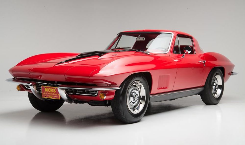
1967 exterior colors for the Corvette were Tuxedo Black, Ermine White, Rally Red, Marina Blue, Lynndale Blue, Elkhart Blue, Goodwood Green, Sunfire Yellow, Silver Pearl, Marlboro Maroon. In terms of production volumes, the split was as follows: Tuxedo Black 815 (3.55%), Ermine White 1,423 (6.20%), Rally Red 2,341 (10.20%), Marina Blue 3,840 (16.74%), Lynndale Blue 1,381 (6.02%), Elkhart Blue 1,096 (4.78%), Goodwood Green 4,293 (18.71%), Sunfire Yellow 2,325 (10.14%), Silver Pearl 1,952 (8.51%) and Marlboro Maroon 3,464 (15.10%).
Pricing & Options
The Base Corvette Coupe with 327 cu. in. 300 hp engine and three speed manual transmission was $4,388, while the Base Corvette Convertible with 327 cu. in. 300 hp engine and three speed manual transmission was $4,240.00. There were plenty of options by 1967 and you can see the production volumes and pricing below. There are tons more detail, and you can see full options and pricing detail here.
|
CODE:
|
DESCRIPTION: | QUANTITY: |
RETAIL PRICE:
|
| 19437 | Base Corvette Sport Coupe | 8,504 | $4,388.00 |
| 19467 | Base Corvette Convertible | 14,436 | $4,240.00 |
| 402 | Genuine Leather Seats, Black | – | $79.00 |
| 408 | Genuine Leather Seats, Red | – | $79.00 |
| 415 | Genuine Leather Seats, Medium Bright Blue | – | $79.00 |
| 419 | Genuine Leather Seats, Dark Teal Blue | – | $79.00 |
| 421 | Genuine Leather Seats, Medium Saddle | 11,331 | $15.80 |
| A01 | Soft Ray Tinted Glass, All Windows | $6,558.00 | $10.55 |
| A02 | Soft Ray Tinted Glass, Windshield | 4,036 | $57.95 |
| A31 | Power Windows | 1,762 | $42.15 |
| A82 | Headrests | 1,426 | $26.35 |
| A85 | Shoulder Belts | 6,880 | $231.75 |
| C07 | Auxillary Hardtop (for convertibles) | 1,966 | $52.70 |
| C08 | Vinyl Covering (For Auxiliary Hardtop) | 35 | $97.85 |
| C48 | Heater and Defroster Deletion (credit) | 3,788 | $412.90 |
| C60 | Air Conditioning | 2,198 | $36.90 |
| F41 | Special Front and rear Suspension | 20,308 | $42.15 |
| G81 | Positraction Rear Axle, all ratios | 4,766 | $42.15 |
| J50 | Power Brakes | 267 | $342.30 |
| J56 | Special Heavy Duty Brakes | 2,573 | $44.75 |
| K19 | Air Injection Reactor | 5,759 | $73.75 |
| K66 | Transistor Ignition System | 3,832 | $200.15 |
| L36 | 427ci, 390hp Engine | 2,101 | $305.50 |
| L68 | 27ci, 435hp Engine | 3,754 | $437.10 |
| L79 | 327ci, 350hp Engine | 6,375 | $105.35 |
| L88 | 427ci, 430hp Engine | 20 | $947.90 |
| L89 | Aluminum Cylinder Heads for L71 | 16 | $368.65 |
| M20 | 4-Speed Manual Transmission | 9,157 | $184.35 |
| M21 | 4-Speed Manual Transmission, Close Ratio | 11,015 | $184.35 |
| M22 | 4-Speed Manual Trans., Close Ratio, Heavy Duty | 20 | $237.00 |
| M35 | Powerglide Automatic Transmission | 2,324 | $194.35 |
| N03 | 36 Gallon Fuel Tank (for coupe) | 2 | $198.05 |
| N11 | Off Road Exhaust System | 2,326 | $36.90 |
| N14 | Side Mount Exhaust System | 4,209 | $131.65 |
| N36 | Telescopic Steering Column | 2,415 | $42.15 |
| N40 | Power Steering | 5,747 | $94.80 |
| N89 | Cast Aluminum Bolt-On Wheels (5) | 720 | $263.30 |
| P92 | Whitewall Tires, 7.75 x 15 | 13,445 | $31.35 |
| QB1 | Redline Tires, 7.75×15 | 4,230 | $46.55 |
| U15 | Speed Warning Indicator | 2,108 | $10.55 |
| U69 | AM-FM Radio | 22,193 | $172.75 |
Read more: 1967 Corvette pricing and factory options.
1967 Corvette Gallery
Though styling changes were minimal, the revisions followed the trend of slightly refining the second-generation Corvette to make it look cleaner and sleeker. Five small front fender vents took the place of the previous larger three, and for the first time a single backup light above the license plate was used. New wheel covers also were included with the new models. See full 1967 Corvette Image Gallery
I have a 67 roadster,327/350 4 speed….I want to reduce the RPM’s, at higher speeds, which will help with noise and heat.
Options presented was add 5th gear, change transmission, or just change the gears. I wanted more speed but less energy used, plus better gas millage…any suggestions or other options.
please add me to all c2 1967 info past present and future THANKS
What does 3900200 paint in white along with production date of 9/26/67? I have a green coupe 4 sod the carb side pipe car
do you know how many 1967 conv green with tan interior 327 300hp 4 speeds with power windows where made tiring to track down one i bought new in the boston area ( salem mass )
Thanks Al
what ratio does it have now.plenty of higher gear options.