

1965 Corvette Overview – The Ultimate Guide
As the 1965 model year approached, the design team behind the Chevy Corvette continued to refine the overall design of the C2 Sting Ray, making only minor cosmetic changes in the process. Instead, the focus for the second-generation’s third year centralized on some significant mechanical upgrades that would vastly improve the Corvette’s already impressive handling and drivability.
At the same time, 1965 would also mark the beginning of the end of the second-generation Corvette as Zora Arkus-Duntov and Bill Mitchell each began championing the effort to develop a third-generation Corvette, although each would bring with him a different interpretation of what that next-generation car would be.
Duntov’s group was actively seeking out ways to develop a mid- or rear-engine Corvette that was synonymous with cars like Porsche’s mid-engine Carrera GTS coupe.
By contrast, Mitchell’s team had a different vision, one that would be fully realized in the development of the Mako II Concept vehicle, a car that would eventually become known as one of the most famous concept vehicles of all time.
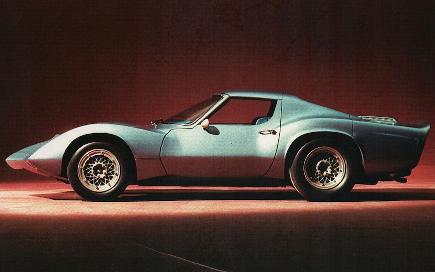
For Duntov, the vision was to design a true mid-engine Corvette that could support a big-block Mark IV engine riding just ahead of the rear wheels. Duntov’s group developed a shape for their car’s fiberglass body, and even went so far as to assemble a couple of small-scale models in early 1965.
DID YOU KNOW: The 1965 Mako Shark II was originally called just the “Mako Shark.” However, the moniker was changed to “Mako Shark II” after it was decided to retroactively rename the XP-755 prototype the “Mako Shark I”.
Ultimately, however, a rear- or mid-engine Corvette demanded specific mechanical components that General Motors simply did not provide. While the company had repeatedly attempted to produce a transaxle that was able to withstand the torque of a high-power V-8 engine, the design and the tooling expenses required to develop one that would be used only in a low-volume model would have sent Corvette prices skyrocketing beyond control.
Still, it was decided that if General Motors could not entice consumers with a car that provided leading-edge technology, then Mitchell and company would introduce them to a car that had exotic styling.
Bill Mitchell had actually begun laying out the next generation Corvette in late 1964 with the help of Larry Shinoda and the General Motor’s design division. The intent from the onset had been to develop a car that could travel the auto-show circuit to serve as a trial balloon for the next generation Corvette.
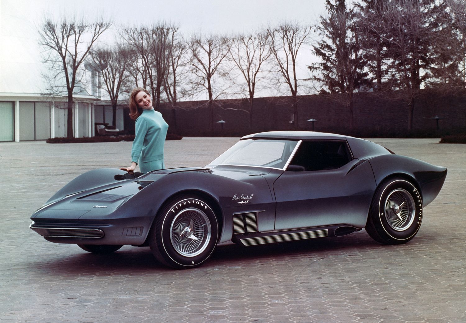
Mitchell instructed Shinoda that a suitable preview would have to be ready for the New York International Auto Show before April, 1965. In response to Mitchell’s request, Shinoda’s team of designers developed a full-size mock up of Mitchell’s next vision for the Chevy Corvette, which they dubbed the “Mako Shark II” (so named because of its long, somewhat flattened front-end, which made the car resemble a shark.)
The mock-up, which lacked an engine despite the hood label that read “Mark IV 396”, was rolled out for press release photography in March, 1965. A fully functional Mark Shark II would follow shortly thereafter, fitted with a 427-cubic-inch Mk IV big-block V-8 engine.
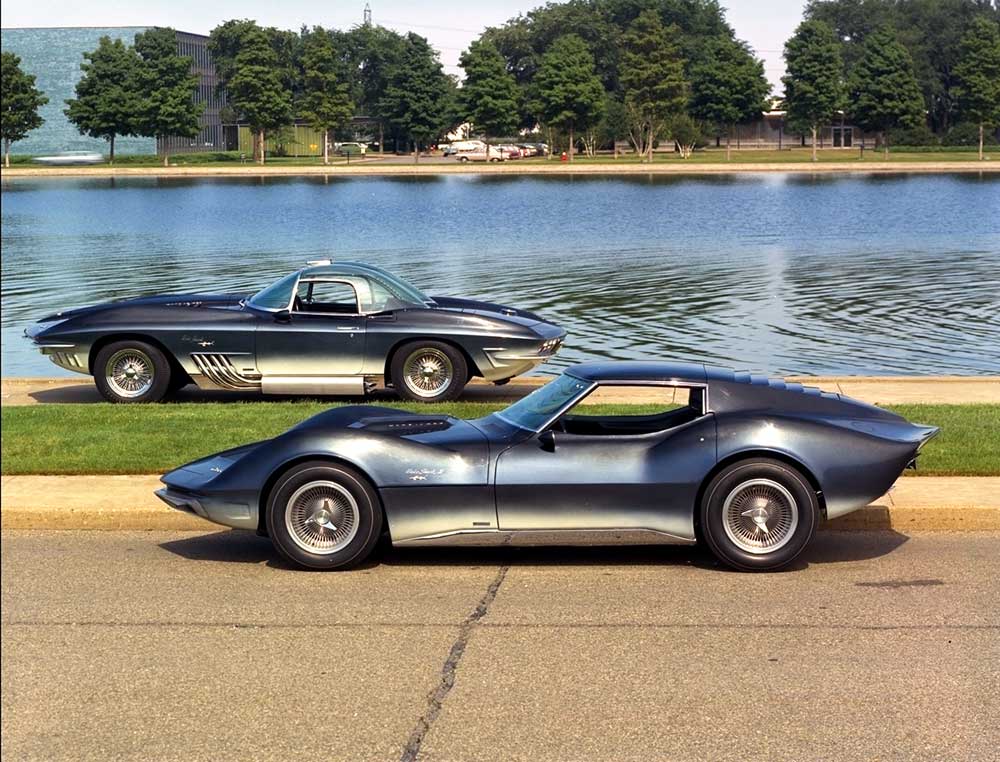
Whether viewing the mock-up or the actual prototype, there was no question that the car looked fast. An aggressively pointed prow gave way to a domed hood that signified robust power. In both the mockup and the prototype, the bulging wheelhouses at all four corners of the Corvette only enhanced the already aggressive appearance of the car.
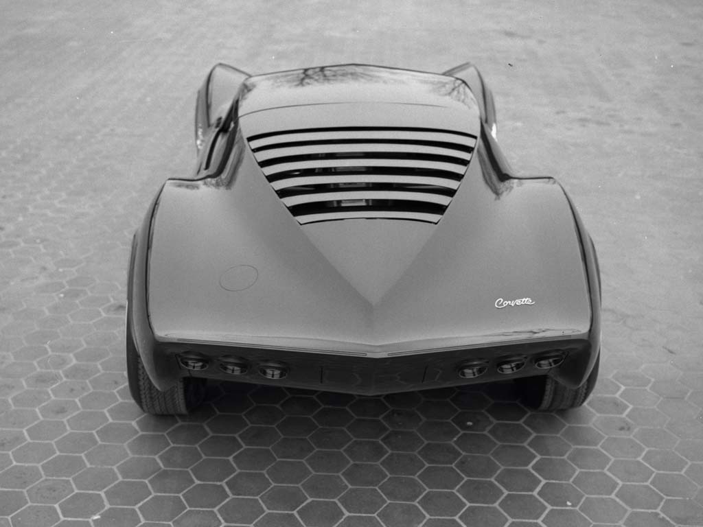
Large, wide Firestone tires were wrapped around the wheels. The mockup featured cast-aluminum side exhaust with finned sidepipes that were painted in crackle black with “fins” which maintained a bright, polished finish.
Changes to this exhaust system were made after the cars unveiling at the New York Auto Show (prior to the elimination of the side exhaust system from the prototype car completely.)
Measuring three inches longer than the existing Sting Ray, the “Mako Shark II” featured a sleek roof -line that rolled back into a tapered exclamation point. That same bodyline continued all the way to the rear of the car, where a pronounced ducktail design defined the rear of the car. The entire car was painted using a careful feathering/blending of colors which only further helped to enhance the appearance that the “Shark II” was some sort of other-worldly design.
Using a blend of browns, blues (including Firefrost Midnight Blue) and grays, the car really started to represent the magnificent beasts of the sea from which so much inspiration was drawn for the car’s design.
Even with the development of a new Corvette underway, the current, second-generation Corvette still had the immediate attention of Chevrolet’s executives. Given the sales success of the first two model years, there was little doubt by anyone that the 1965 Corvette would be equally successful, or perhaps even surpass previous successes. Given that fact, and the fact that Corvette’s best designers were focused on supporting the development of the next generation Corvette, Chevrolet was not making major modifications to the current model.
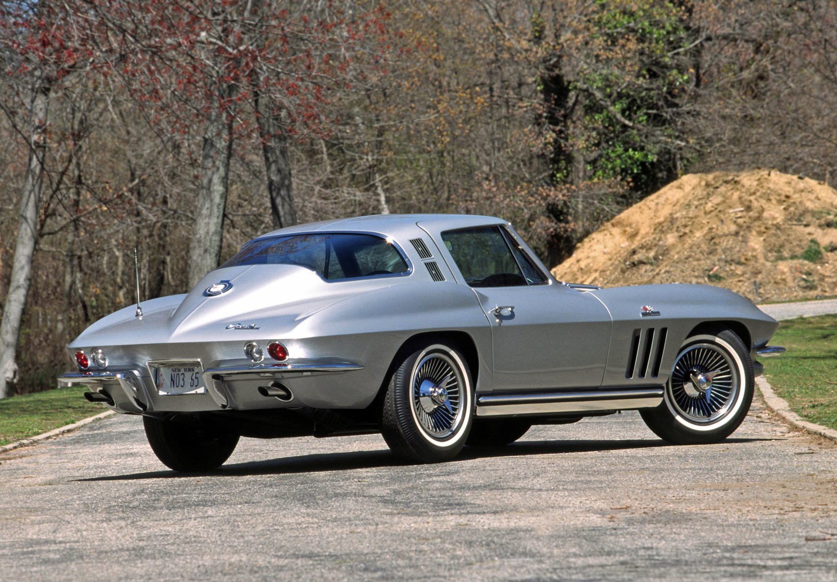
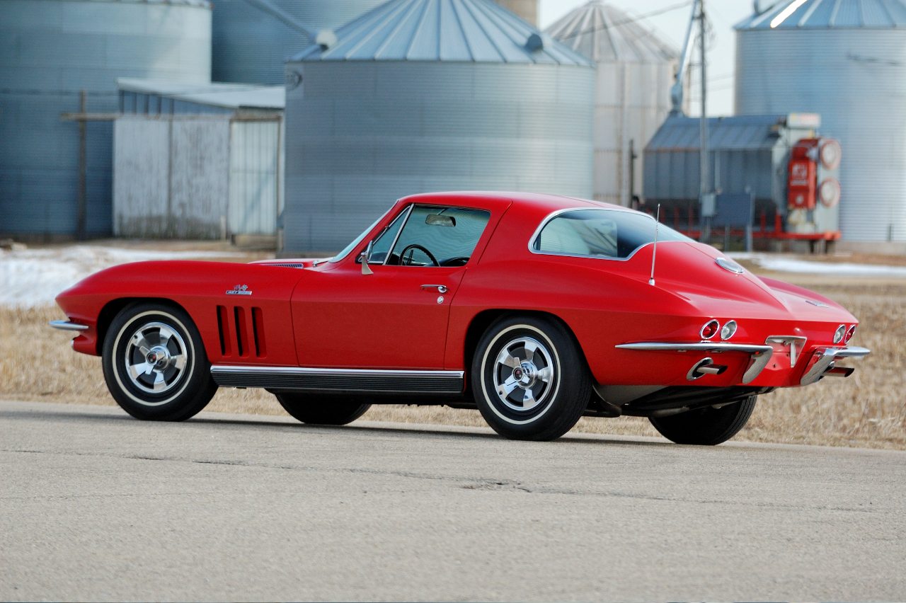
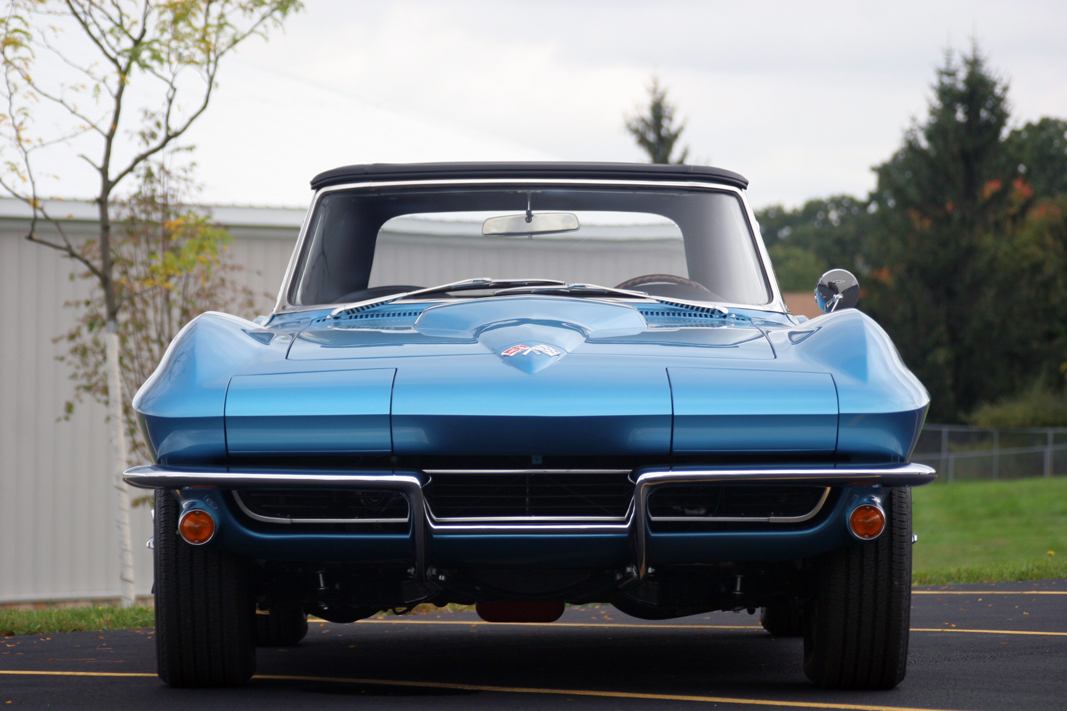
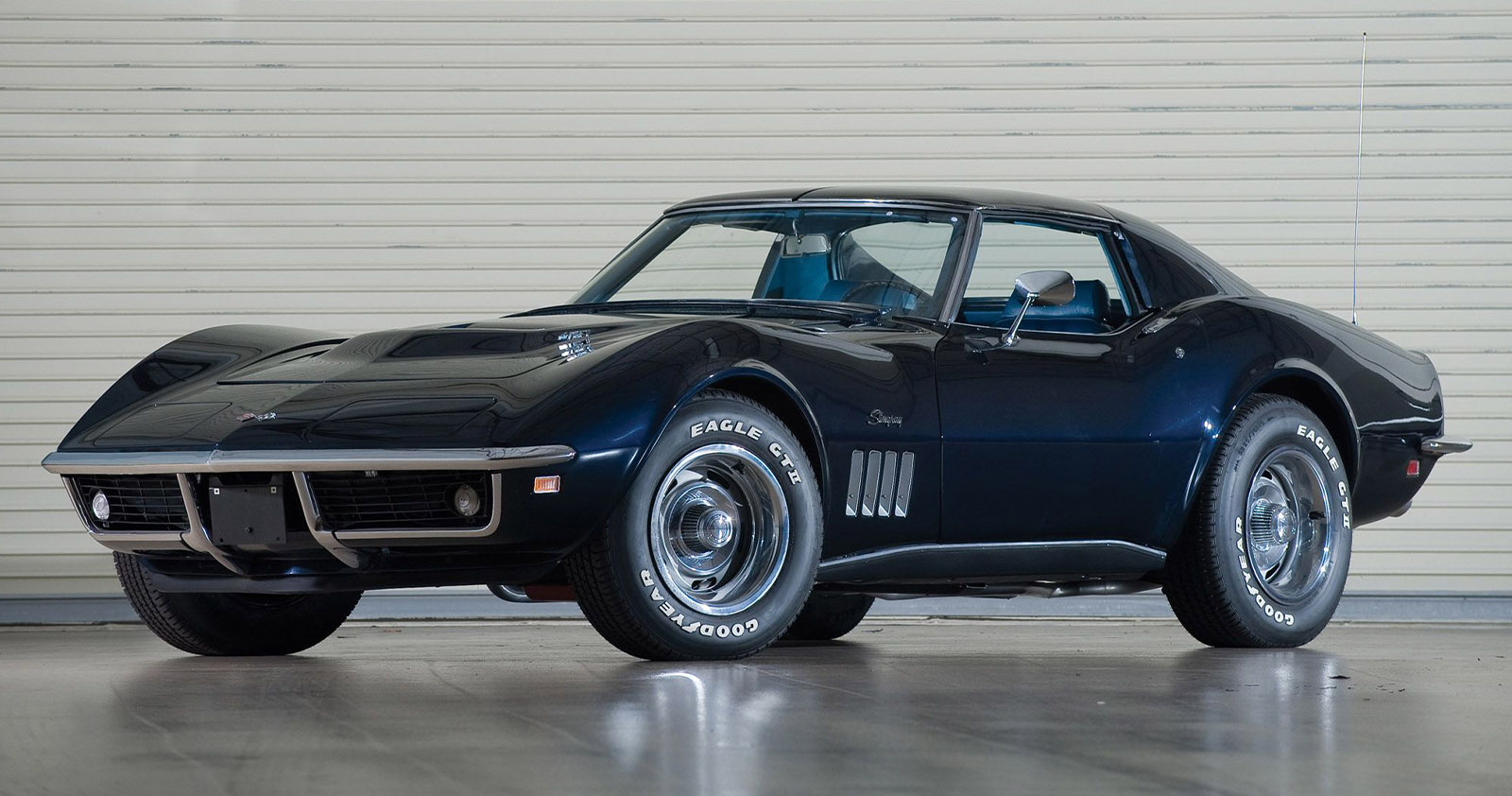
That’s not to say there weren’t any changes made to the Corvette’s appearance. The most notable change to the outward appearance of the car was the removal of the former scoop indentations, which had carried over in the 1964 model (after the faux hood scoops were removed from the 1963 design.)
The new hood, which was now a single, smooth surface, became one of the major differentiating characteristics of the 1965 model year. In addition, the front fenders were redesigned to feature a trio of working exhaust vents (which replaced the previous model’s non-functional horizontal “speedline” coves.)
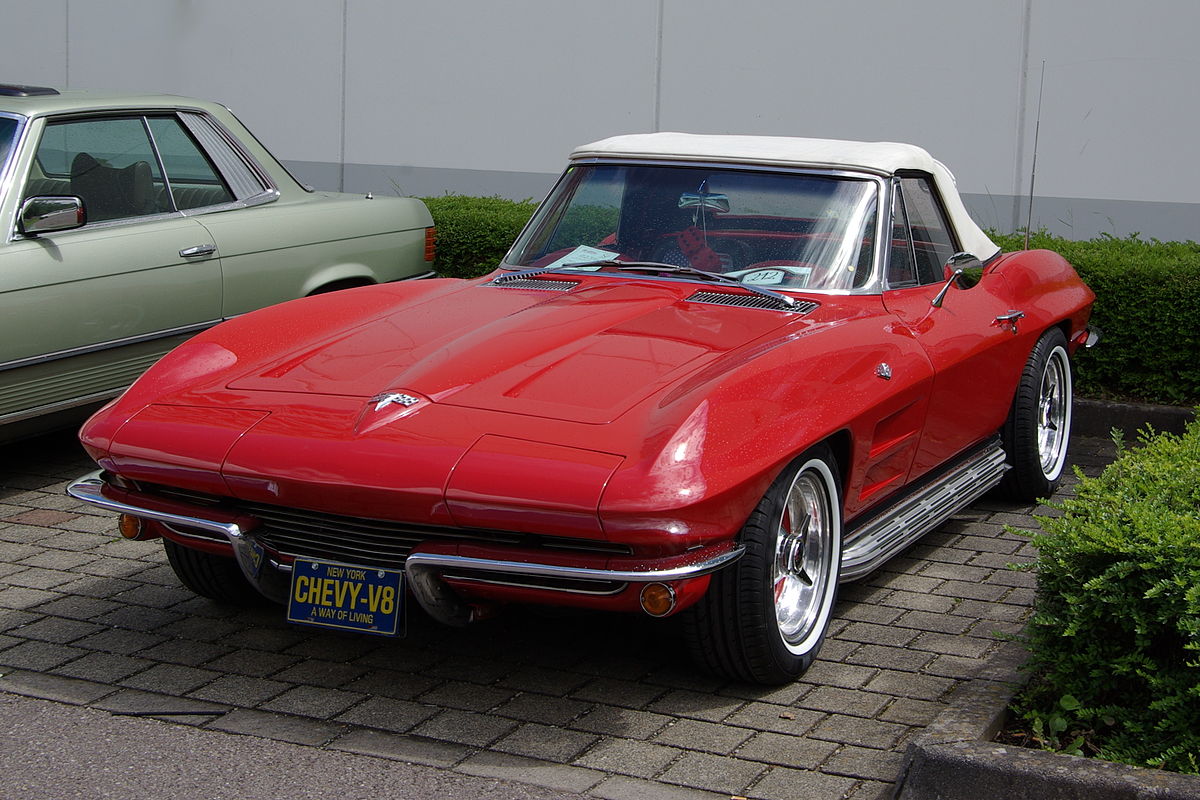
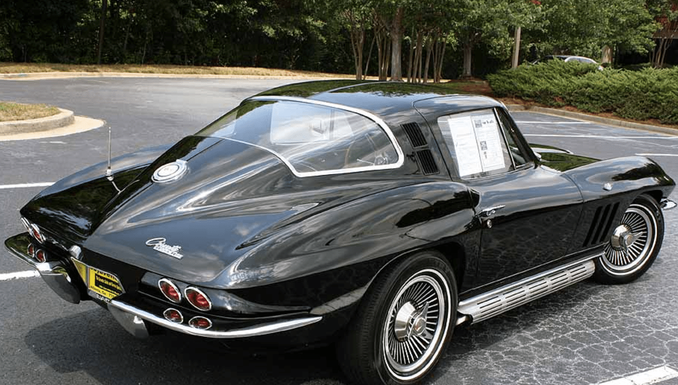
Another notable design change involved refinements to the front grill. For the 1965 model treatment; the inner, horizontal grill bars were painted black, but the outer grill remained a bright chrome color, making the overall design unique to the 1965 Corvette. Lastly, the wheel covers and rocker-panel moldings were re-designed for the 1965 model year. The optional knock-off wheel covers now featured a dark gray paint color between the fins.
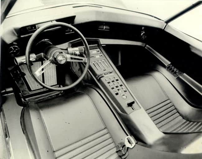
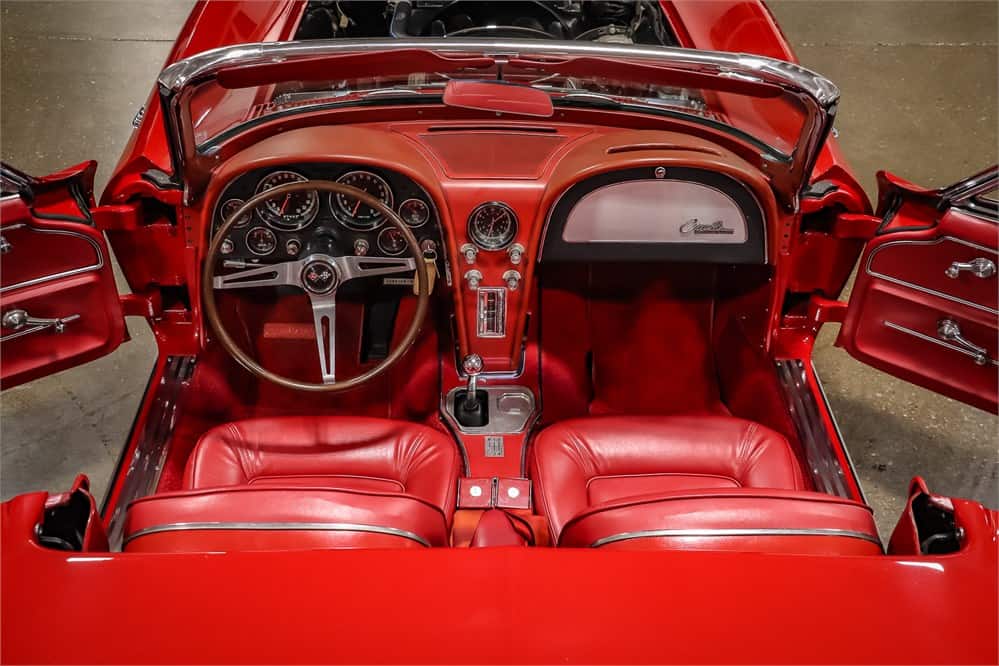
The interior of the car also received some minor design refinements as well, though these were far more subtle than those made to the Corvette’s exterior. In the driver’s dashboard, all of the instrument displays were redesigned to include flat black faces.
Elsewhere, the areas around the radio and speaker bezel were now being painted, instead of utilizing the vinyl covering that had been standard on previous models. A more notable improvement involved another change in the design of the car’s driver and passenger seats. The new seating surfaces were designed to be slightly larger and more supportive, and the seat backs were now encased in hard plastic backing shells. Complementing the newly evolved seats, the inner door panels were also redesigned and now included fully integrated armrests. Lastly, the interior received new seat belt retractors, a feature that was never before been seen in a Corvette.
While these changes were important to the continued evolution of the Corvette, the focus on the 1965 model year had really been directed at correcting many of the elements found below the car’s fiberglass exterior.
A number of noteworthy alterations and additions were made for the 1965 model year – some of which would set a precedence that would carry over to the most current Corvette models being built today. The first of these welcome additions was the introduction of a standard, four-wheel.
The brakes featured a four-piston design with two piece calipers mated to a newly designed brake rotor which utilized cooling fins. The cooling fins helped to dissipate the massive amount of heat being generated during hard braking.
Suspended between the calipers and rotors was an all new semi-metallic brake pad. These pads were designed to remain in constant contact with the brake rotors which aided in keeping the braking surfaces on the rotor free from rust and debris (both of which cause pitting and diminish the lifespan of any brake rotor.)
While the drag created by the contact between the pads and rotors was negligible, the benefits of maintaining the rotor condition helped GM to project a life expectancy of 57,000 miles on the front braking system (which, because of the forward weight transfer, supplied most of the braking effort in all-out stops.) Better still, the expected lifespan of the rear brakes was twice that of the front. Pending federal regulations (at/during the development phase of the 1965 Corvette), a dual master cylinder with separate fluid reservoirs for front and rear lines was also introduced. The newly designed master cylinder helped reduce the overall temperature of the brake fluid, which contributed to brake failure in older models.
The disc brakes were a much needed improvement over the previous braking system. Prolonged testing of the new disc brake system found that repeated stops from 100 miles per hour did not cause any deterioration in the efficiency of the braking system. Equally important was the fact that no matter the condition, all stops were very stable and required a much shorter braking distance than the earlier drum brakes. Despite this, the old drum brake system did remain available to consumers and garnered a $64.50 credit on the overall Corvette purchase price when selected as an option. Despite this, only 316 Corvettes built in 1965 came equipped with the drum brake option.
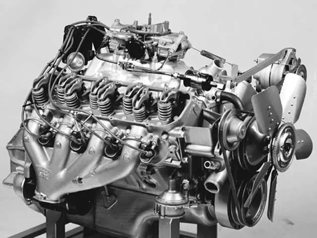
Another significant improvement and mechanical milestone arrived midway through the 1965 model year. Officially titled the Mark IV, Chevrolet introduced a new, optional, big-block V-8 engine for the first time in a production Corvette. The Mark IV had actually originated in early 1963 as the “mystery” 427 racing engine that had made its first appearance at the Daytona 500. Despite its official title, the engine was marketed as the Turbo Jet and was made available in three varieties, two 396 cubic inch versions, and a 427 (although a fourth, “heavy-duty” 427 was also created for marine use.)
The 396 big-block engines were scheduled to replace Chevy’s hallowed, though short-lived 409 cubic-inch by Semon E. “Bunkie” Knudsen (then General Manager of Chevy) that the only viable investment was to develop the most modern engine available, Chevy’s engine plant in Tonawanda, New York was retooled to support the production of the Mark IV engine. The engine officially began production in mid-1965.
A number of variants of the Mark IV engine were produced. For its mid-size Chevelle model and all full-size Chevy models, a 325 horsepower and 360 horsepower engine was produced.
For the Corvette, however, the engine, which was available to consumers under RPO L78, was given 11:1 compression, impact-extruded alloy pistons with chrome rings, solid lifters, a bigger carburetor (and corresponding double-snorkel air cleaner) and an oversized oil pump, all of which helped make this more radical Mark IV engine capable of producing an impressive 425 horsepower.
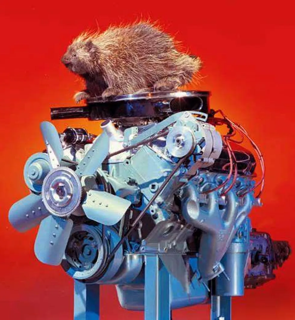
The big-block also featured free-breathing cylinder heads with staggered valves that had been laid out in a seemingly disorganized fashion, with an appearance reminiscent to porcupine quills, which earned the engine the nickname, ‘the porcupine motor.”
The Mark IV engine was an immediate sensation and brought Corvette enthusiasts to their local Chevrolet dealerships in droves. While its introduction late in the model year resulted in limited supply, there was no questioning the long-term potential for an engine that was capable of producing such impressive performance numbers.
Even when equipped with a moderate 3.70:1 rear axle, a Mark IV equipped Corvette could do a standing quarter mile run right around 14 seconds at an impressive 104 miles per hour. Further, given adequate track distance, the car could now reach an overall top speed of nearly 140 mph (again when equipped with the 3.70:1 axle-ratio.)
Aside from the late-entry Mark IV, several other engines had remained available for the 1965 model year including a 375 horsepower, 327 cubic-inch small-block V8 that came equipped with fuel injection.
While this small-block engine was an impressive powerhouse in its own right, Chevrolet had definitely recognized that the direction of the powerplant for the Corvettes would center around engine displacement, and so it was decided that all other, smaller engines would ultimately be abandoned in the Corvette line at the end of the 1965 model year. Interestingly, the retirement of the 327ci engine also brought with it the end of the use of fuel injection in Corvettes for the next twenty years.
Another new engine did appear in 1965 however. The L79 small block, which was essentially an L76 327 engine featuring a slightly milder hydraulic cam in place of the solid-lifter stick. Operating on an 11:1 compression ratio, the L79 engine was rated at 350 horsepower, and was deemed nearly identical to the L76 on the outside with its chromed air cleaner and finned cast-aluminum valve covers.
Production Volumes
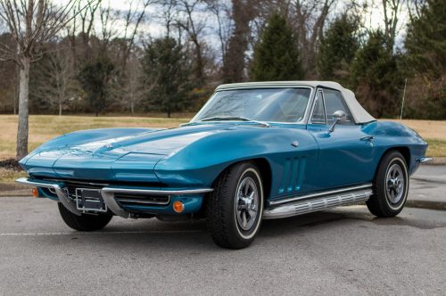
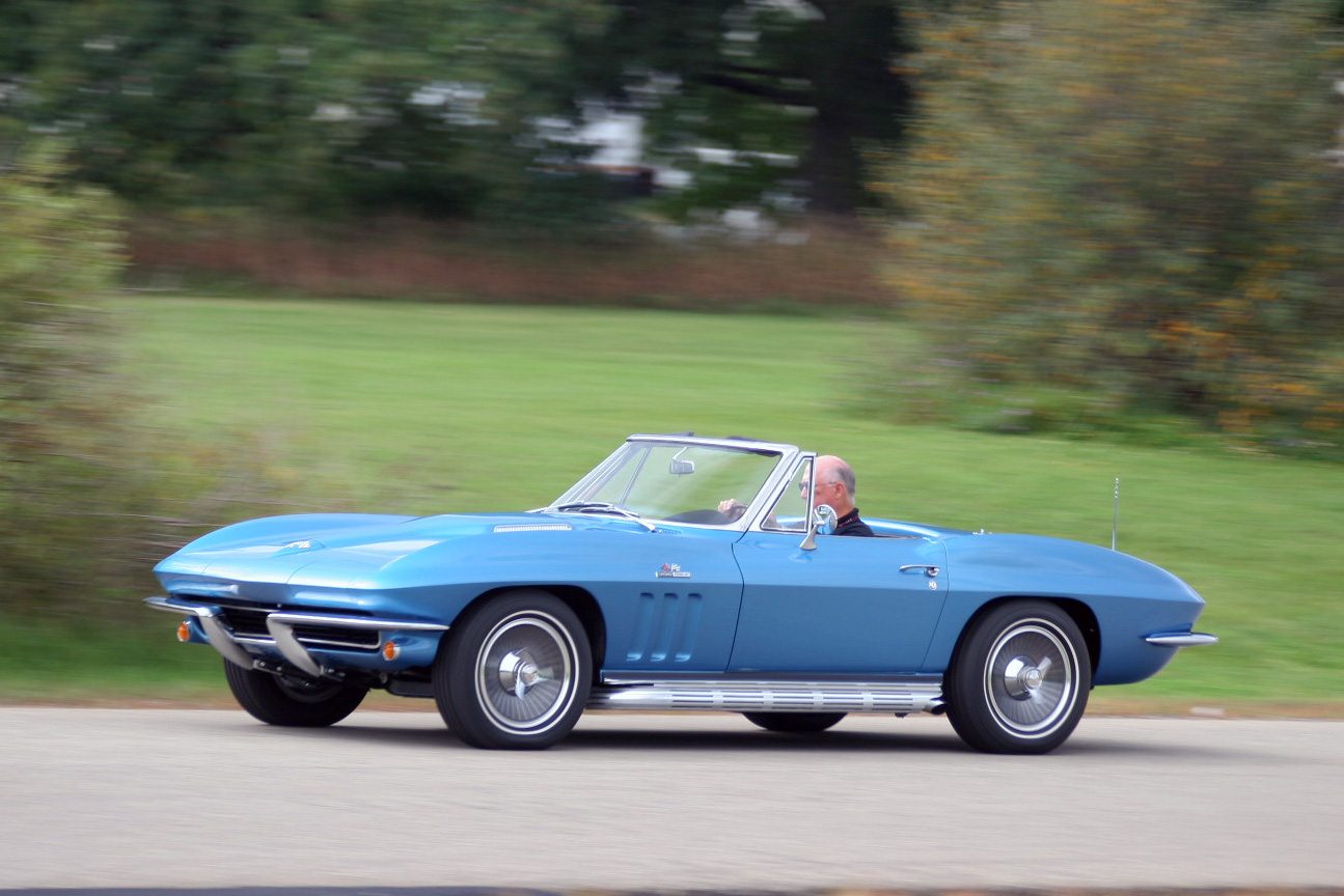
In all, the 1965 Sting Ray saw a total of 23,564 units sold, making 1965 the most successful sales year for the Corvette yet. Of all the units built, 15,378 were convertibles, accounting for nearly two-thirds of all Corvettes sold in 1965. By comparison, the coupe sold a mere 8,186 units.
1965 Corvette Specifications & Performance
Engine & Transmission
The 1965 Corvette represented Chevrolet’s continued investment in the Corvette’s performance, with buyers able to choose from six different engines and three transmission options. Horsepower ranged from 250 hp in the base 327 ci V8 all the way up to a monstrous 425 horsepower from the L79 V8. See all 1965 Corvette engine & technical specifications.
Performance
Several publications tested the 1965 Corvette. Road and Track tested the 1965 Corvette (396ci/425hp) and hit 0 – 60 mph in just 5.7 seconds and the quarter mile in just 14.1 seconds. Car Life and Motor Trend also tested the same set up and basically got the same numbers. See more performance data here.
1965 Corvette Vehicle Identification Numbers (VIN)
The last six digits begin at 100001 and run through 123564, accounting for all 23,564 Corvette Coupes/Convertibles built in 1965. Two Corvettes were built after production officially ended. Each Vehicle Identification Number (VIN) is unique to an individual car. For all 1965 Corvettes, the location of the Vehicle Identification Number (VIN), body style, body number trim and paint combination can be found on the instrument panel brace under the glove box. Get more details in our 1965 Corvette VIN numbers guide.
1965 Corvette Price & Options
Core Features & Factory Options
The big news for 1965 was not how the outside of the car looked, but rather what was under the hood. The new 396 CID V8 was by far the largest engine ever installed in a Corvette, and consequently had the most horsepower of any Corvette in history. And the introduction of the bigger engine would be a sign of things to come – as the engines would grow even larger in 1966.
But for 1965, the other engines were all forms of the 327 CID V8. Base Corvettes had a 327 that was rated at 250 horsepower, but there were also three modified versions of the engine. One was rated at 300 horsepower, while the other used a different carburetor, a Holley, to bump up the rating to 365 horsepower. But the top of the 327’s was the fuel-injected engine, which produced 375 horsepower. The downside of this engine, however, was that it added $726 to the base price of the car, while the new 396 added only $481.
Most Corvette fans welcomed the newly standard four-wheel disc brakes, though the car did come with the option of a $64.50 credit to those who chose to eliminate this standard feature. 316 Corvettes were ordered without the disc brakes in 1965. Other than the new bucket seats and the leather seating option, the interior of the car stayed largely the same for 1965 as well.
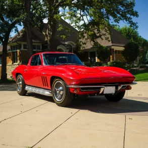
Colors
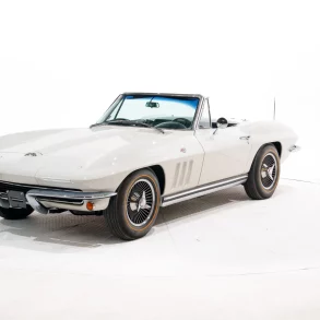
1965 Corvette colors included Tuxedo Black, Ermine White, Nassau Blue, Glen Green, Milano Maroon, Silver Pearl, Rally Red, Goldwood Yellow. The most popular color was Nassau Blue with almost 26% of cars being made in that hue. Glen Green (16%), Rally Red (15.7%) and Milano Maroon (12%) were also popular in 1965. See more details on 1965 colors.
Pricing & Options
The Base Corvette Coupe with 327 cu. in. 250 hp engine and three speed manual transmission is $4,321, and the Base Corvette Convertible with 327 cu. in. 250 hp engine and three speed manual transmission started at $4,106. Below we have most, if not all, of the options available when ordering a new 1965 Chevrolet Corvette. Also included are the interior and exterior color options, including paint codes. Read more: 1965 Chevrolet Corvette Pricing, Factory Options, & Colors.
| CODE: | DESCRIPTION: | QUANTITY: |
RETAIL PRICE:
|
| 19437 | Base Corvette Sport Coupe | 8,186 | $4,321.00 |
| 19467 | Base Corvette Convertible | 15,377 | $4,106.00 |
| 402 | Genuine Leather Seats, Black | – | $80.70 |
| 408 | Genuine Leather Seats, Red | – | $80.70 |
| 415 | Genuine Leather Seats, Blue | – | $80.70 |
| 421 | Genuine Leather Seats, Saddle | – | $80.70 |
| 427 | Genuine Leather Seats, Silver | – | $80.70 |
| 431 | Genuine Leather Seats, Green | – | $80.70 |
| 436 | Genuine Leather Seats, Maroon | – | $80.70 |
| 438 | Genuine Leather Seats, White, (Black Instrument & Carpet) | – | $80.70 |
| 451 | Genuine Leather Seats, White, (Red Instrument & Carpet) | – | $80.70 |
| A01 | Genuine Leather Seats, White, (Blue Instrument & Carpet) | – | $16.15 |
| A02 | Soft Ray Tinted Glass, All Windows | 7,624 | $10.80 |
| A31 | Soft Ray Tinted Glass, Windshield | 3,809 | $59.20 |
| C07 | Power Windows | 7,787 | $236.75 |
| C48 | Auxillary Hardtop (for convertibles) | 39 | $100.00 |
| C60 | Heater and Defroster Deletion (credit) | 2,423 | $421.80 |
| F40 | Air Conditioning | 975 | $37.70 |
| G81 | Special Front and Rear Suspenion | 19,965 | $43.05 |
| G91 | Positraction Rear Axle, all ratios | 1,886 | $2.20 |
| J50 | Special Highway Axle, 3.08:1 ratio | 4,044 | $43.05 |
| J61 | Power Brakes | 316 | -$64.50 |
| K66 | Drum Brakes (substitution credit) | 3,686 | $75.35 |
| L75 | Transistor Ignition System | 8,358 | $53.80 |
| L76 | 327ci, 300hp Engine | 5,011 | $129.15 |
| L78 | 327ci, 365hp Engine | 2,157 | $292.70 |
| L79 | 396ci, 425hp Engine | 4,716 | $107.60 |
| L84 | 327ci, 350hp Engine | 771 | $538.00 |
| M20 | 327ci, 375hp Engine (fuel injection) | 21,107 | $188.30 |
| M22 | 4-Speed Manual Transmission | 30 | $171.00 |
| M35 | 4-Speed Manual Trans., Close Ratio, Heavy Duty | 2,021 | $199.10 |
| N03 | Powerglide Automatic Transmission | 41 | $202.30 |
| N11 | 36 Gallon Fuel Tank (for coupe) | 2,468 | $37.70 |
| N14 | Off Road Exhaust System | 759 | $134.50 |
| N32 | Side Mount Exhaust System | 2,259 | $48.45 |
| N36 | Teakwood Steering Wheel | 2,259 | $43.05 |
| N40 | Telescopic Steering Column | 3,236 | $43.05 |
| P48 | Power Steering | 1,116 | $322.80 |
| P91 | Cast Aluminum Knock-Off Wheels (5) | 168 | $15.70 |
| P92 | Blackwall Tires, 7.75 x 15 (nylon cord) | 19,300 | $31.85 |
| T01 | Whitewall Tires, 7.75 x 15 (rayon cord) | 989 | $50.05 |
| U69 | Goldwall Tires, 7.75 x 15 (nylon cord) | 22,113 | $203.40 |
| Z01 | AM-FM Radio | 15,397 | $16.15 |
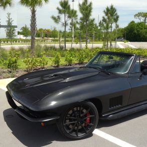
1965 Corvette Image Gallery
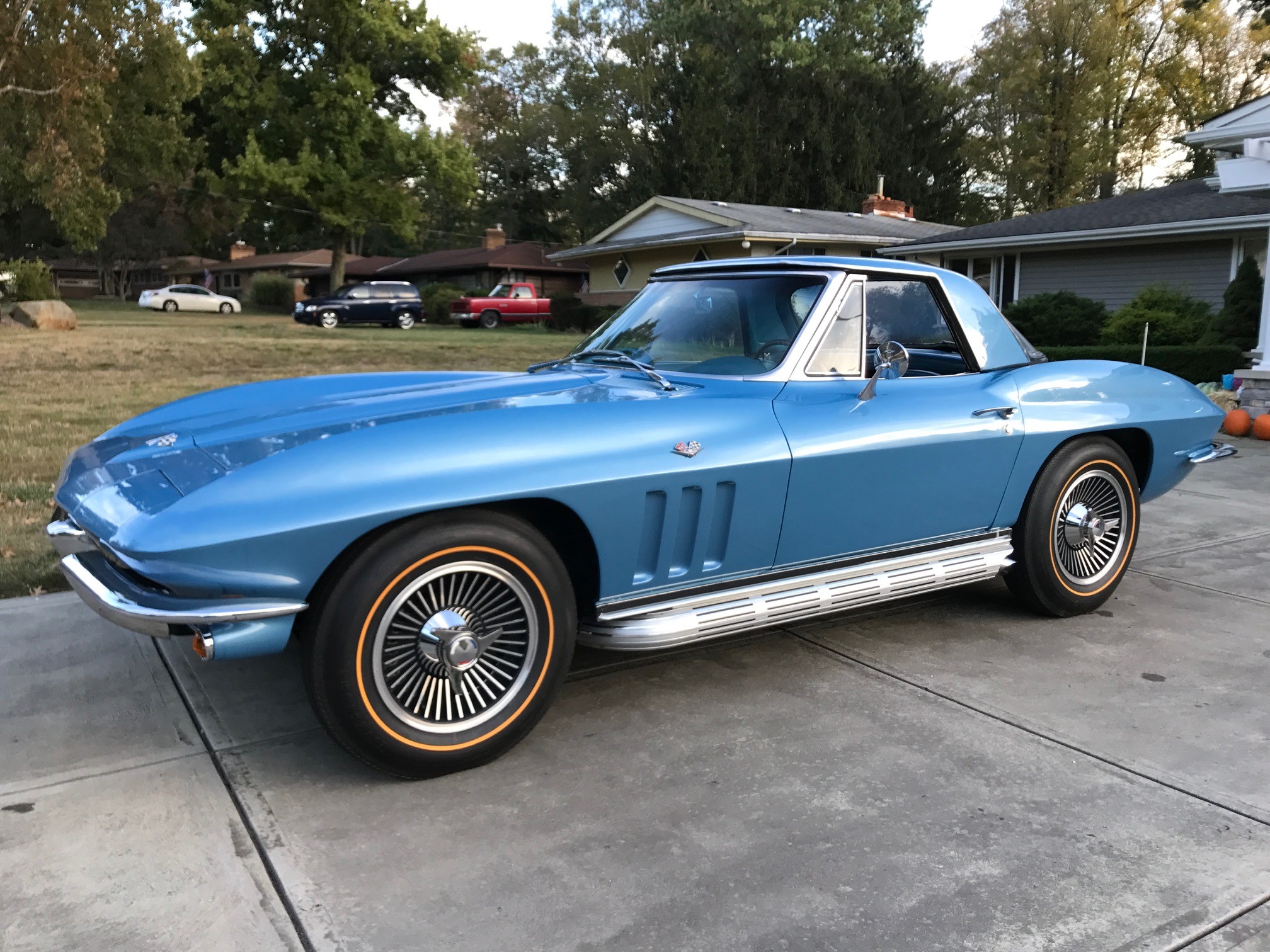
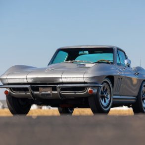
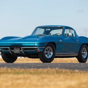
At first glance, the 1965 Corvette doesn’t look much different from the 1964 models, or the 1963 models, for that matter. But a closer look reveals that Corvette styling was evolving in the same way it always had, through subtle styling changes every year that continued to refine the look of an already stylish car. See full 1965 Corvette Image Gallery


Check the 396 bore/stroke, it can’t be the same as the 327 😉
The 4 speed transmission numbers I.e. M21 & M22 Don’t seem correct. Also, in the braking section, it states a dual circuit master cylinder was used. My 65 has a single circuit unit.
Much of your options list doesn’t reflect the correct options for what it is supposed to match. Engine code for 350 and 365 hp, 396/425 hp, tire info, Z01 Convenience Gp, etc, etc. Proof reading seems non-existant. A lot of good info corrected.
Power brakes had dual circuit, manual brakes had single.