NOTICE: While Corvsport.com has made every effort to ensure that the instruction provided on this site is both complete and accurate, it is presented here for REFERENCE ONLY. All vehicle maintenance and repairs should only be performed by a qualified technician or mechanic and should not be attempted without the proper tools and/or experience. Improperly performed vehicle repair can result in damage, injury, and even death. User discretion is advised.
COOLING SYSTEM CARE
The radiator cap should not be removed to check coolant level. Check the coolant level visually in the see thru coolant recovery tank whenever the hood is up. When the engine is cold, the coolant level should be near the “ADD” line on the reservoir. At normal operating temperature, the coolant level should increase to the “FULL” mark on the recovery tank. If coolant is not at this level during operating conditions, coolant should be added only to the reservoir to raise the level to the “FULL” mark. Use a 50/50 mixture of high-quality ethylene glycol anti-freeze and water when adding coolant.
The cooling system should be serviced as follow:
Wash radiator cap and filler neck with clean water.
Check coolant for proper level and freeze protection.
Pressure test system and radiator cap for proper pressure holding capacity – 103 kPA (15 psi). If replacement of cap is required, use the proper cap specified.
Tighten hose clamps and inspect all hoses. Replace hoses whenever cracked, swollen or otherwise deteriorated.
Clean frontal area of the radiator core and the air conditioning condenser.
DRAINING AND RE-FILLING
The cooling system should be flushed and re-filled using the following recommended procedure.
Remove the radiator cap ONLY WHEN THE ENGINE IS COOL by:
1.) Slowly rotating the cap counter-clockwise to detent. (Do not press down while rotating).
2.) Wait until any residual pressure (indicated by a hissing sound) is relieved.
3.) After all hissing ceases, press down on the cap while continuing to rotate counter-clockwise.
CAUTION: To avoid the danger of being burned, do not remove the radiator cap while the engine and radiator are still hot. Scalding radiator fluid and steam may be blown out under pressure.
Open radiator drain valve and block drain plugs to drain coolant.
Close valve, install block drain plugs, and add sufficient water to fill system.
Run engine, drain and re-fill the system (as described in the previous steps) a sufficient number of times until the drained liquid is nearly colorless.
Allow system to drain completely and then close the radiator drain valve tightly, and install block drain plugs.
Remove recovery cap leaving loses in place. Remove coolant recovery tank and empty fluid. Flush tank with clean water, drain, and re-install.
Add sufficient ethylene glycol coolant. Fill the radiator to the base of the radiator fill neck and add sufficient coolant to the recovery tank to raise the level to the “FULL” mark. Reinstall recovery tank cap.
Run the engine with the radiator cap removed until normal operating temperature is reached. (The upper radiator hose will become hot.)
With engine idling, add coolant until level reaches the bottom of the filler neck and install the radiator cap making certain that the arrows line up with the overflow tube.
It is the owner’s responsibility to keep the freeze protection at a level proportionate with the temperatures which may occur in the area of vehicle operation.
Maintain cooling system freeze protection at -37 degrees Celsius (-34 degrees Fahrenheit) to ensure protection against corrosion and loss of coolant from boiling even when freezing temperatures are not expected.
Add ethylene glycol base coolant when coolant additions are required because of coolant loss or to provide additional protection against freezing at temperatures lower than -37 degrees Celsius (-34 degrees Fahrenheit).
NOTE: Alcohol or methanol base coolants or plain water are not recommended at any time. Adding anti-freeze to prevent the coolant from boiling too soon is permissible but too much will affect the freezing point. A solution stronger than 70% anti-freeze should never be used, as the freeze level rises rapidly after this point. Pure anti-freeze will freeze at -8 degrees Celsius (-20 degrees Fahrenheit.)
COOLANT SYSTEM DIAGNOSIS
If the cooling system requires frequent addition of coolant in order to maintain the proper level, check all units and connections in the cooling system for evidence of leakage. Inspection should be made with the cooling system cold. Small leaks which may show dampness or dripping can easily escape detection when the engine is hot, due to the rapid evaporation of coolant. Tell-take signs of grayish white or rusty color, or dye stains from anti-freeze at joints in cooling system are almost always sure signs of small leaks even though there appears to be no damage.
Air may be drawn into the cooling system through leakage at the water pump seal or through leaks on the coolant recovery system. Gas may be forced into the cooling system through leakage at the cylinder head gasket(s) even though the leakage is not sufficient to allow coolant to enter the combustion chamber.
SYSTEM CHECKS
Exhaust Leaks
To check for exhaust leaks into the cooling system, drain the system until the coolant level stands just above the top of the cylinder head(s), ten disconnect the radiator upper hose and remove the thermostat and accessory belt. Start the engine and quickly accelerate several times. At the same time, note any appreciable coolant rise or the appearance of bubbles which are indicative of exhaust gases leaking into the cooling system.
NOTE: A defective head gasket may allow exhaust gases to leak into the cooling system. This is particularly damaging to the cooling system as the gases combine with the water to form acids which are harmful to the radiator and the engine.
Water Pump
The water pump’s operation may be checked by running the engine while squeezing the radiator’s upper hose (with the engine warm). A pressure surge should be felt. Check for a plugged venthole in the pump is a surge is not felt.
Removal
Disconnect the negative battery cable.
Drain the cooling system.
Remove the drive belt.
Remove the water pump pulley.
Remove the AIR pump pulley.
Remove the air management valve adapter.
Remove the AIR pump.
Disconnect the fuel inlet and return lines.
Remove the rear A/C compressor braces.
Remove the lower A/C compressor mounting bolt.
Remove A/C compressor and idler pulley bracket nuts.
Disconnect A/C compressor wires.
Slide mounting bracket forward and remove rear A/C compressor bolt.
Remove A/C compressor.
Remove right and left AIF hoses at check valve.
Remove AIR pipe at intake and power steering reservoir bracket.
Remove power steering reservoir bracket including the top alternator bolt.
Remove lower AIR bracket on water pump.
Remove lower radiator and heater hose at water pump.
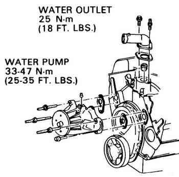
Remove water pump.
Installation
If installing a new water pump, transfer the heater hose fitting from the old unit.
With clean sealing surfaces on both block and water pump, install the water pump to the engine block with new gaskets and retain with the attaching bolts. Torque to 25-35 ft. lbs.
Reverse removal procedures for the remaining installation steps.
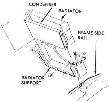
RADIATOR
Test for restriction in the radiator by warming the engine up, turning the engine off, and then feeling the radiator. The radiator should be hot along the left side and warm along the right side, with an even temperature rise from right to left. Cold spots in the radiator indicate clogged sections
Removal
Disconnect negative battery cable.
Drain cooling system.
Remove upper radiator hose.
Remove lower radiator hose.
Remove overflow hose at radiator.
Remove A/C accumulator and move aside.
Remove transmission cooler line.
Remove fan wires from fan and shroud.
Remove fan to gain access to lower cooler line.
Remove transmission cooler line at fitting.
Remove upper shroud bolts.
Remove upper shroud.
Remove radiator.
Installation
Place radiator on lower support.
Install transmission lower cooler line.
Install upper shroud.
Install fan.
Install fan wires.
Install transmission upper cooler lines.
Install upper and lower radiator hoses.
Install overflow hose.
Install A/C accumulator.
Fill cooling system.
Start engine and run with radiator cap removed until upper radiator hose becomes hot (thermostat open).
With engine idling, add coolant to radiator until level reaches bottom of filler neck.
Install the filler cap.
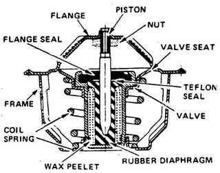
THERMOSTAT
An operation check of the thermostat can be made by hanging the thermostat on a hook in a 33% glycol solution 22 degrees (Fahrenheit) above the temperature stamped on the thermostat valve. Submerge the valve completely and agitate the solution thoroughly. Under this condition the valve should open. Remove the thermostat and place in a 33% glycol solution 10 degrees (Fahrenheit) below temperature indicated on the valve. With the valve completely submerged and coolant agitated thoroughly, the valve should close completely.
Removal
Disconnect negative battery cable at the battery.
Remove air cleaner.
Drain cooling system.
Remove upper radiator hose from outlet.
Remove thermostat housing attaching bolts and remove housing.
Remove thermostat from manifold.
Installation
Prior to installing the thermostat, make sure the manifold and thermostat housing mating surfaces are clean and free of any residual gasket material.
Place a 1/8″ bead of RTV sealant (or equivalent) all around the thermostat housing sealing surface on the intake manifold.
Place thermostat in the intake manifold.
Install the thermostat while sealant material (RTV sealant or equivalent) is still wet.
Torque remaining bolts to 18-23 ft. lbs.
Install the air cleaner and connect negative battery cable.
Fill the cooling system.o
Start the engine and allow it to run, with the radiator cap removed, until the upper radiator hoses become hot.
With the engine idling, add coolant to the radiator until the fluid level reaches the bottom of the filler neck.
Install the radiator cap, making sure that the arrows line up with the overflow tube.
OVERHEATING AND/OR NOISE
No Subscription? You’re missing out
Get immediate ad-free access to all our premium content.