Get Ad-Free Access: Just $39/year

The 1984 Corvette DIY Guide – Battery/Charging System

1984 Corvette

The 1984 Corvette DIY Guide – Battery/Charging System

See full 1984 Corvette Overview and Image Gallery

BATTERY & CHARGING SYSTEM

NOTICE: While Corvsport.com has made every effort to ensure that the instruction provided on this site is both complete and accurate, it is presented here for REFERENCE ONLY.  All vehicle maintenance and repairs should only be performed by a qualified technician or mechanic and should not be attempted without the proper tools and/or experience.  Improperly performed vehicle repair can result in damage, injury, and even death.   User discretion is advised.
GENERAL ELECTRICAL SYSTEM DIAGNOSIS
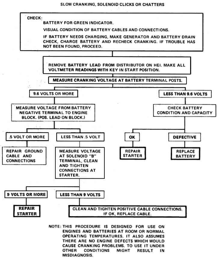
The engine electrical system diagnosis includes the battery, the starter, and the generator/alternator (and related wiring.)  The following diagnosis charts will aid in troubleshooting system faults.  When a fault is traced to a particular component, refer to the corresponding system repairs as defined on this page.   Please utilize the links at the top of the page to find service instructions for each system.

BATTERY
A sealed battery is standard on all Corvettes.  There are no vent plugs in the cover.  The battery is completely sealed, except for two  small vent holes in the side.  These vent holes allow the small amount of gas produced in the battery to escape.  The battery has the following advantages over conventional batteries:
  • No water addition for the life of the battery.
  • Overcharge protection.  If too high a level voltage is applied to the battery, it will not accept as much current as a conventional battery.  In a conventional battery, the excess voltage will still try to charge the battery leading to gassing, which causes liquid loss.
  • Not as liable to self-discharge as compared to a conventional battery.  This is particularly important when a battery is left standing for long periods of time.
  • More power available in a lighter and smaller case.
The battery has three major functions in the electrical system:
  • It is a source of electrical energy for cranking the engine.
  • It acts as a voltage stabilizer for the electrical system.
  • It can, for a limited time, provide energy when the electrical load used exceeds the output of the generator/alternator.
COMMON CAUSES OF FAILURE
The battery is not designed to last indefinitely.  However, with proper care, it will provide many years of service.  If the battery tests good but fails to perform satisfactorily in service for no apparent reason, the following are some of the more important factors that may point to the cause of trouble:
  • Accessories are left on overnight.  This could include leaving a cell phone charger (or similar device) plugged into the accessories outlet.
  • Slow average driving speeds for short periods.
  • the vehicle electrical load is more than the generator output particularly with the addition of after market equipment (such as stereo amplifiers, extra speakers, etc.)
  • Defects in the charging system such as electrical shorts, slipping fan belt, faulty generator or voltage regulator.
  • Battery abuse, including failure to keep the battery cable terminals clean and tight or loose battery hold down.
  • Mechanical problems in the electrical system such as shorted or pinched wires.
  • Freezing conditions, although the freezing point of electrolyte depends on it’s specific gravity.  Since freezing may ruin a battery, it should be protected against freezing by keeping it in a charged condition.
BUILT-IN HYDROMETER
The sealed battery has a built-in temperature compensated hydrometer in the top of the battery.  This hydrometer is to be used with the following diagnostic procedure.  When observing the hydrometer, make sure that the battery has a clean top.  A light my be needed in some poorly lit areas.
Under normal operation, two indications can be seen:
  • GREEN DOT VISIBLE: Any green appearance is interpreted as a “green dot” and the battery is ready for testing.
  • DARK; GREEN DOT NOT VISIBLE: If there is a cranking complaint, the battery should be tested.  The charging and electrical systems should also be checked at this time.
Occasionally, a third condition may appear:
  • CLEAR OR LIGHT YELLOW:  This means the fluid level is below the bottom of the hydrometer.  This may have been caused by excessive or prolonged charging, a broken battery case, excessive tipping or normal battery wearout.  When finding a battery in this condition, it may indicate high charging voltage caused by a faulty charging system and therefore, the charging and electrical system may need to be checked.  If a cranking complaint exists and is caused by the battery, it should be replaced.
DIAGNOSIS
The following procedure should be used for testing batteries:
1.) VISUAL INSPECTION
  • Check for obvious damage, such as cracked or broken case or cover, that could permit loss of electrolyte.  If obvious damage is noted, replace the battery.  Determine cause of damage and correct as needed.  If not, proceed to step 2.
2.) HYDROMETER CHECK
  • If GREEN DOT VISIBLE, proceed to step 3.
  • if DARK; GREEN DOT NOT VISIBLE, then charge the battery and proceed to step 3.
3.) LOAD TEST
NOTE: Load testing may require the use of battery side terminal adapters to insure good connections.
  • Connect a voltmeter and a battery load tester across the battery terminals.
  • Apply 300 ampere load for 15 seconds to remove surface charge from the battery.  Remove load.
  • Wait 15 seconds to let battery recover and apply specified load from load test chart (see below.)  Read voltage after 15 seconds then remove load.
  • If voltage does not drop below the minimum voltage listed (see below), the battery is good and should be returned to service.  Temperature of the battery will change the minimum voltage to pass the load test.  When performing this step, estimate the temperature that the battery has been exposed to for the last several hours.

BATTERY REPLACEMENT
  • Disconnect Negative battery cable.
  • Disconnect Positive battery cable.
  • Remove battery hold down clamp.
  • Follow “Fender Reposition” graphic (below) for battery removal.
  • Lift battery up and out of vehicle.
  • Reverse this procedure to install.
  • Torque battery cables to 19lb/ft.


BATTERY CHARGING
When it is necessary to charge the battery, the following safety precautions must be followed:
  • DO NOT CHARGE the battery if the hydrometer is clear or light yellow.Replace battery.
  • If the battery feels hot (greater than 52 degrees Celsius (125 degrees Fahrenheit)), or if violent gassing or spewing of electrolyte through the vent hole occurs, discontinue charging or reduce charging rate.


CHARGING PROCEDURE
  • Batteries with a green dot showing do not require charging unless they have just been discharged (such as in cranking the engine.)
  • When charging sealed-terminal batteries out of a vehicle, install adapter kit ST-1201or GM Part No, 1846855, or equivalent.  Post-style batteries require no adapters.
  • Make sure all charger connections are clean and tight.
  • For best results, batteries should be charged while electrolyte and plates are at room temperature. A battery that is extremely cold may not accept current for several hours after starting charging.
  • Charge battery until a green dot appears.  The battery should be checked every half-hour while charging.  Tipping or shaking the battery may be necessary to make the green dot appear.
  • After charging, the battery should be tested as outlined in the section BATTERY DIAGNOSIS (See Above).
JUMP STARTING WITH AUXILIARY BATTERY (OR BOOSTER PACK)
NOTICE: Do not push or tow the vehicle to start.  damage to the emission system and/or to other parts of the vehicle may occur.  Also, both the booster pack (or auxiliary battery) and the discharged battery should be treated carefully when using jumper cables.  Follow the procedures outlined below.  Avoid producing sparks.
CAUTION:  Departure from the directions/conditions listed below could result in: 1.) Serious personal injury (particularly to the eyes) or property damage as the result of such causes as a battery explosion, battery acid, or electrical burns.  Additionally, damage to a battery (as those defined herein) may result in damage to other electronic components of both the vehicle being jump started as well as the car providing the jump (in instances where a battery to battery jump start is attempted.)
  • Never expose an automotive (or any) battery to an open flame or electric spark.  Batteries generate a gas which is both flammable and explosive.
  • Remove rings, watches and other jewelry whenever handling a battery.  Wear approved eye protection.
  • Do not allow battery fluid to contact eyes, skin, fabrics, or painted surfaces – battery fluid is a corrosive acid.  Flush any contacted area with water immediately and thoroughly.  Be careful that metal tools or jumper cables do not contact the positive battery terminal (or metal in contact with it) and any other metal on the car, because a short circuit could occur.  Batteries should always be kept out of the reach of children.
  • Set parking brake and place automatic transmission in “PARK” (“NEUTRAL” for manual transmissions.)  Turn off ignition, turn off lights and all other electrical loads.
  • Check the built-in hydrometer.  If it is clear or light yellow, replace the battery.
  • Attach one end of the jumper cable to the positive terminal of the booster battery and the other end of the same cable to the positive terminal of the discharged battery.  Do not permit vehicles to touch each other as this could cause a ground connection and counteract the benefits of this procedure.  (NOTE: Only use a 12-Volt battery to jump start the vehicle.)
  • Attach one end of the remaining negative cable to the negative terminal on the booster battery, and the other end to a solid engine ground (such as an A/C compressor bracket or generator mounting bracket) at least 18 inches from the battery of the vehicle being started.  (NOTE:  DO NOT CONNECT DIRECTLY TO THE NEGATIVE TERMINAL OF THE DISCHARGED/DEAD BATTERY.)
  • Start the engine of the vehicle that is providing the jump start and turn off the electrical accessories.  Then start the engine in the car with the discharged battery.
  • Reverse these directions exactly when removing the jumper cables.  the negative cable must be disconnected from the engine that was jump started first.
CHARGING SYSTEM
The basic charging system is the SI integral regulator charging system.  The generator used is a 17 SI type.  The 17 SI generators have delta stator windings and cannot be checked for opens.  The generator features a solid state regulator that is mounted inside the generator.  All regulator components are enclosed into a solid mold and this unit, along with the brush holder assembly, is attached to the slip ring end frame.  The regulator voltage setting cannot be adjusted. No periodic adjustments or maintenance of any kind is required on the entire generator assembly.
DIAGNOSIS
To avoid damage to your internally regulated generator, always follow these precautions:
  • Do not reverse connections to the generator.
  • Do not short across or ground any of the terminals in the charging circuit except as directed by instructions.
  • NEVER operate the generator with the output terminal disconnected.
  • When connecting a charger or a booster battery to the vehicle, follow the procedures outlined in the “Battery Charging Section” .
Trouble in the charging system will show up as one or more of the following conditions:
  • Out of normal range voltmeter reading.
  • An undercharged battery as evidenced by slow cranking or the hydrometer “eye” showing black/dark.
  • An overcharged battery as evidenced by excessive spewing of electrolyte from the vents.
UNDERCHARGED BATTERY
This condition, as demonstrated by slow cranking or a dark hydrometer can be caused by one or more of the following conditions (even though the indicator lamp may be operating normally.)  The following procedures also apply to cars with a voltmeter:
  • Ensure that the undercharged battery condition has not been caused by accessories left on for extended periods.
  • Check the drive belt for proper tension (See “Belts/Hoses” for more information on adjusting tension.)
  • Inspect the wiring for defects.  Check all connections for tightness and cleanliness, including the slip connectors at the generator and bulkhead, and the battery cable connections at the battery, the starter and the ignition ground.
  • With the ignition switch “on” and all wiring harness leads connected, connect a voltmeter from:
a.) Generator “BAT” terminal to ground.
b.) Generator No. 1 terminal to ground.
c.) Generator No. 2 terminal to ground.
  • A zero reading indicates an open between the voltmeter connection and the battery.  Generators have a built-in feature which avoids overcharging of the battery and accessory damage by preventing the generator from turning on if there is an open in the wiring harness connected to the No. 2 (sensing) generator terminal.
If the above steps check satisfactorily, proceed to check the generator as follows:
  • Disconnect the negative battery cable.
  • Connect an ammeter or generator tester in the circuit at the “BAT” terminal of the generator.
  • Reconnect the negative battery cable.
  • Turn on radio, windshield wipers, lights high beam and blower motor on high speed.  Connect a carbon pile across the battery (or use the generator tester).
  • Maintain an engine speed of about 2,000 RPM and adjust carbon pile as required to obtain the maximum current output.
  • If ampere output is within 10 amperes of rated output as stamped on generator frame, generator is not defective.  In this instance, re-check Steps 1 through 5.
  • If ampere output is not within 10 amps of the rated output, determine if the test hole is accessible.
  • Ground the field winding by inserting a screwdriver into the test hole.  Tab is within 19mm (3/4 inch) of the casting surface.  Do not force the screwdriver deeper than one inch (25 mm) into the end frame to avoid damaging the generator.
  • Operate engine at moderate speed as required, and adjust carbon pile as required to obtain maximum current output.
  • If output is within 10 amperes of rated output, check field winding, diode trio, and rectifier bridge, and test the regulator with an approved regulator tester.
  • If output is not within 10 amperes of rated output, check the field winding, diode trio, rectifier bridge, and stator.
OVERCHARGED BATTERY
  • To determine battery condition, refer to the “Battery Diagnosis” Section above.
  • If an obvious overcharge condition exists (as evidenced by an illuminated flag in the voltmeter of the instrument cluster), proceed to check the field windings for grounds and shorts.  If defective, replace rotor, and test the regulator with an approved regulator tester.
NOTE:  There are a number of automotive/auto parts stores that provide free generator/alternator testing to their customers.  If you are inexperienced at performing the type of diagnostic work defined in this section, it is recommended that you utilize the services of one of these automotive facilities.
GENERATOR REMOVAL, INSTALLATION, and ON-CAR SERVICE
  • Disconnect the battery ground cable (generally the BLACK cable.)
  • Remove the air cleaner flex duct.
  • Remove the adjusting brace bolt.
  • Loosen the generator mounting bolts.
  • Position the generator to ease belt tension and remove the belt from the generator pulley.
  • Remove the generator mounting bracket thru bolt and remove the generator.
  • Reverse this procedure for installation.
The generator does not require periodic lubrication.  The rotor shaft is mounted on ball bearings at the drive end and roller bearings at the slip ring end, and each contains a permanent grease supply.  At periodic intervals, check the mounting bolts for tightness and adjust the belt tension.
  • When adjusting belt tension, apply pressure at the center of the generator, never against either end frame.