The information contained on this page is for reference only and may contain incomplete or outdated information. Read more: 1979 Corvette guide.
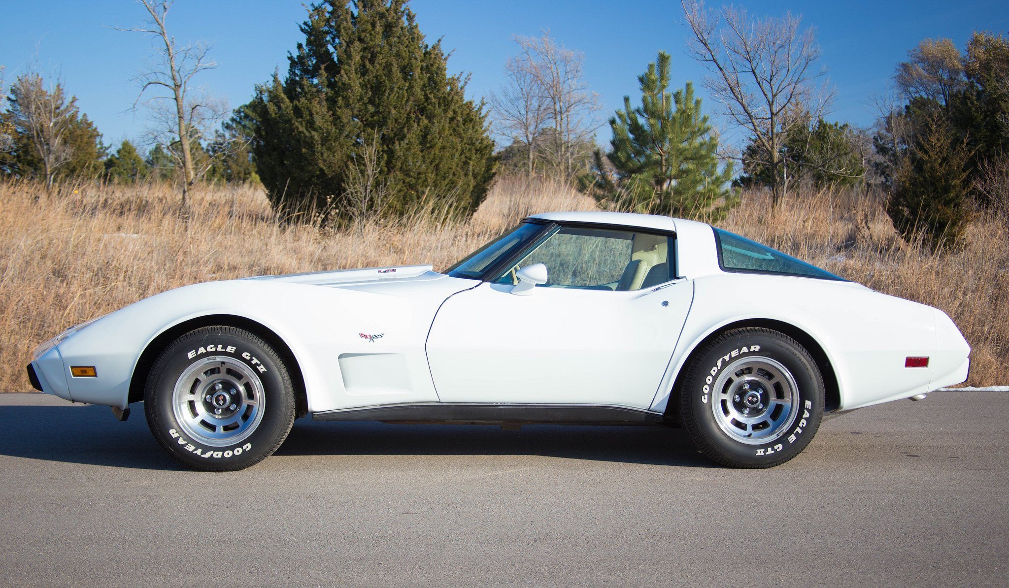
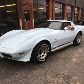
1979 Corvette Recalls
Recall 03E032000
Make: CHEVROLET
Model: CORVETTE
Model Year: 1979
Manufacturer: CARDONE INDUSTRIES, INC.
Mfr’s Report Date: MAY 07, 2003
NHTSA CAMPAIGN ID Number: 03E032000
NHTSA Action Number: N/A
Component: SERVICE BRAKES, AIR:DISC:CALIPER
Potential Number of Units Affected: 15899
No Subscription? You’re missing out
Get immediate ad-free access to all our premium content.
Get Started