The information contained on this page is for reference only and may contain incomplete or outdated information. Read more: 1971 Corvette guide.
1971 Corvette Recalls
Recall 03e032000
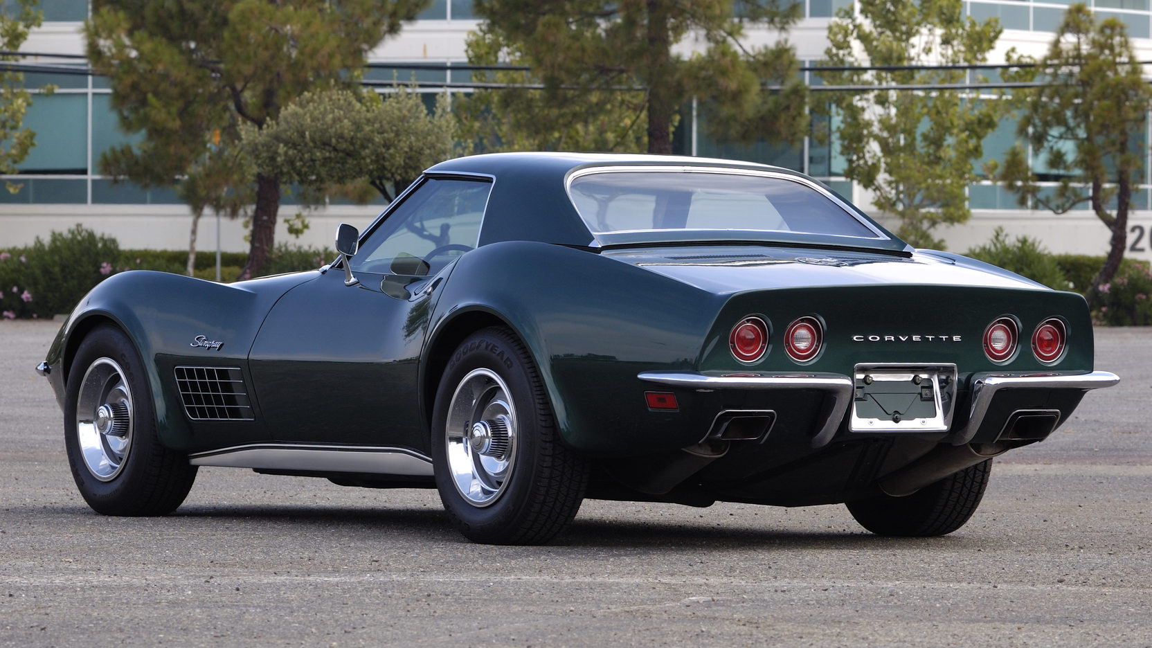
Make: Chevrolet
Model: Corvette
Model Year: 1971
Manufacturer: Cardone Industries, Inc.
Mfr’s Report Date: May 07, 2003
Nhtsa Campaign Id Number: 03e032000
Nhtsa Action Number: N/a
Component: Service Brakes, Air:disc:caliper
Potential Number Of Units Affected: 15,899
Summary: Remanufactured Rear Brake Calipers, Part Nos. 18-7019, 18-7020, 16-7019, And 16-7020, Manufactured From February 1, 2002, To April, 25, 2003., And For Use On 1965 Thru 1982 Chevrolet Corvettes. The Subject Brake Calipers Were Manufactured Using Improperly Manufactured Piston Seals. These Seals Are Intended To Prevent Fluid Leakage Between The Caliper Housing And The Pistons. These Brake Calipers Are For Use Only On 1965 Thru 1982 Chevrolet Corvette Vehicles. This Recall Does Not Involve General Motors Corporation Or Any Of Its Products.
Consequence: Under These Conditions, The Vehicle Operator May Not Be Able To Stop The Car, Possibly Resulting In A Vehicle Crash.
Remedy: Cardone Will Notify Its Customers And All Unsold Inventory Will Be Repurchased And Will Provide A Full Refund To Customers. Owner Notification Is Expected To Begin During May 2003. Owners Who Take Their Vehicles To An Authorized Dealer On An Agreed Upon Service Date And Do Not Receive The Free Remedy Within A Reasonable Time Should Contact Cardone At 215-912-3000.
Notes: Also, Customers Can Contact The National Highway Traffic Safety Administration’s Auto Safety Hotline At 1-888-dash-2-dot (1-888-327-4236).
No Subscription? You’re missing out
Get immediate ad-free access to all our premium content.
Get Started