Get Ad-Free Access: Just $39/year

Guide: “Pull Key, Wait 10 Sec” Service Column Lock Issue And Fix

I've curated all the resources and walk you through my own repair

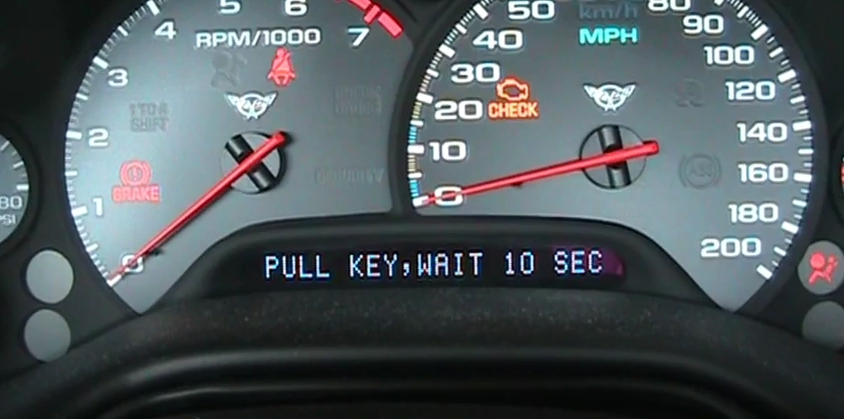
If you own a C5 Corvette and haven’t gotten this error message yet, chances are high that you will if it has not been addressed, as it is one of the most common issues affecting the fifth-generation Corvette. There were adequate previous fixes, and even “dealer fixes” but then the LMC5 module came along and changed the game by providing a “one-stop” fix. I have no affiliation or financial interest with its maker Compliance Parts, it’s just a really good device that works as promised. You can click here for information on ordering.

The following pictures and guide from me are meant to be more of an overview, to augment the excellent and detailed instructions that come with the LMC5 module. I’ve included some helpful tips and suggestions after performing the repair on my 2000 FRC, and there is a Youtube video at the end that helped me put an additional visual on the repair.

First, if you want to read more about the history of the issue and the various fixes and recalls, CorvSport has a resource on mid-year C5 recalls here, and there is a more comprehensive “sticky” FAQ on one of the popular Corvette forums here. Now onto the repair.

Step One: Get all your necessary tools together. The kit comes with the terminal removal tool (a 1.5mm hex key), and you’ll also need some needle nose pliers if you have to remove the #23 fuse (performed if your column locks with the key out). Additional tools are a ratcheting wrench with a 1/4 inch socket, a 5/16 inch socket with the screw-driver type tool, an 8 mm wrench for the side-mounted battery, and a screwdriver will come in handy too.

Step Two: Pull the passenger side floor mat and locate the panel behind it.

Step Three: Pull the panel to gain access to your BCM and fuse panel.

Step Four: If your steering column locks with the key out (like it should if stock), you will need to gain access to the fuse panel. Note that the cover is upside down. Once access is gained, use the chart on the back of the cover to locate the 10 amp #23 fuse. It’s on the top side, left of the 7866 relay.

Once located, turn the key ON, remove the #23 fuse, then remove the key and verify that the steering wheel remains unlocked. DISCONNECT the negative terminal off the battery, and reinsert fuse #23.

Step Five: If you haven’t already done so, disconnect the negative terminal off the battery, then remove the BCM from the compartment. Pull the lower metal tab out first, then unhook it from the top.

Step Six: Remove the lower green connector and the upper large pink one. The LMC5 instructions call to remove the middle one but I really saw no point in doing this. To remove, put your finger on the large blue tab (on the left) and push down to release the connector clip.

The connectors fit rather tightly, so firmly hold the BCM while gently wiggling the connector. Once the green and large pink connectors are removed, take each blue retention clip off. This is done by releasing the two “locking tangs” (see LMC5 instructions if you can’t find them).

Step Seven: It’s highly recommended you remove the steering column lock relay. Some years may not have one, so refer to the LMC5 instructions for specifics. My 2000 FRC did, and the first thing you will note in the Compliance Parts instructions is that he indicates the relay is usually on the right side. Mine was on the left!

How can you make sure you pull the correct one? The wire colors will specifically be orange, orange, green, white, and often purple. I found it hard to unplug the relay while connected above the BCM, so I pulled it off. Once it was free, the tab was easy to find and I finished the task.

Relay location before it was removed
The relay removed and before it was unplugged

Step Eight: Grab the green connector, and face it towards you with the top up (where the blue retention clip was). Locate the orange wire, top row, far left (technically position A8). While holding the connector in your hand, gently push the orange wire toward the connector, ensuring that it is fully seated in the connector.

While holding the green connector and wires in one hand, slowly insert the terminal removal tool (hex key) in the top left hole (A8) about 1/2 inch. To visualize this, I recommend watching the video. Once the tool is inserted, gently pull the orange wire behind it. As the wire is released, note the orientation of the metal terminal.

Step Nine: Take the LMC5 orange wire and match the orientation of the metal terminal with the one you just removed. Gently, but firmly, insert the terminal into the slot at the back of the connector until it snaps into place. DO NOT force it, and once in give it a gentle tug to make sure it is fully seated. No worries if it pops out, as I had this happen on the large pink connection. Just pull it out and turn the orientation around.

Step Ten: Locate the purple wire on the green connector, top row, 3rd from the left (A6). Repeat the same process from step eight, and use the terminal removal tool to release the purple wire. Once released, again notice the orientation, find the purple wire on the LMC5 module, and insert it into the connector. You can now reinstall the blue retention clip on the connector, pushing until the locking tangs snap over the tabs, and gently push it back into the BCM.

Step Eleven: Move to the larger pink connector, remove the blue retention clip, and locate the green wire on the top row, 2nd hole from the right (C15). Note, there are two green wires side by side, with an empty slot at the connector end, so be sure to remove the correct green wire.

Once located, use the same procedure to remove the green wire and replace it with the green wire from the LMC5 module. You can now reinstall the blue retention clip and gently reinsert the pink connector into the BCM. This is also a good time to put the blue caps on the three wires you removed from the connectors.

Step Twelve: Hook up the black ground wire from the LMC5 to the bottom of the BCM. The bolt comes up from the bottom, then the lock washer, then the black wire ring terminal, then the lock nut. You’ll use the 1/4 inch on the bottom and 5/16 inch on the top nut.

Step Thirteen: Place the LMC5 module along with all the wires along the left side of the harnesses, and use the cable ties to secure it. Reinstall the BCM. Reconnect the negative battery cable. You will have the two black caps left over, I don’t know what they are for. Insert the key and turn it on, but do not start the vehicle. Verify the DIC does not display the “pull key, wait 10 sec” or “service column lock” errors. Start the vehicle and check for error messages. Drive the vehicle and make sure you can go faster than 3 mph.

MISSION complete!

If you are like me, I prefer to sit in the comfort of my lazy boy and mentally map out the expectations of a repair, and this video (while not in HD) from Compliance Parts certainly helped. He does it in 10 minutes and says it’s more like 20 minutes. Maybe I’m getting too old for DIY wrenching but it took me 2 hours from start to finish. Granted I had to find and pull the #23 fuse and had some trouble wrestling the steering column lock relay out, but yikes that time is embarrassing.

I hope this guide helps you, we often have vibrant discussions over on our Facebook page, and I would love to hear from you. Have you encountered this problem, and did the fix work?  Douglas B.