
Welcome to a new DIY series where CorvSport canvasses the internet for the best do-it-yourself guides. Let CorvSport be your digital encyclopedia and bring you the best guides and resources from our vast Corvette community. This series can also give an enthusiast contemplating a DIY project the clarity needed to realize they should hire an expert.
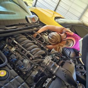
Today’s guide comes from Corvette Forum member “Dope” and answers that question many ambitious wanna-be wrenchers ask: Can I replace the clutch on my C5 while on jackstands? Dope asked himself the question and answered with a resounding, heck yes!
CorvSport Complexity Guide
- Difficulty: 9 (10 most difficult)
- Patience Needed: 10
- Level of Specialty Tools Required: 8
- Is a Helper Recommended? Yes
This curated C5 clutch installation is fully credited to Dope and is being presented to our CorvSport community in an unedited format.
How To Install A Clutch On Your C5
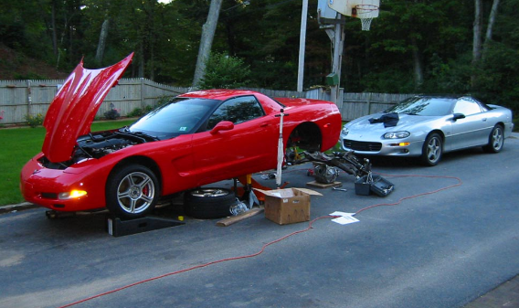
Step 1: Lift your Corvette
First things first, get the car in the air. Higher is better. I drive the front up on ramps, and then jack the rear crossmember quite high (2’+). Jackstands go under the frame rails on the sides. I double up the jackstands and then put the rear wheels/tires under the sides just in case. Like I said, higher is better. If you’ve got a lift, or if you’ve got more jackstands, having the front higher helps even more. It can get a little crowded when doing the actual clutch swap.
Step 2: Preparation for brakes, shocks, and control arms
Remove the rear brake calipers from their brackets (2 15mm bolts each). Stick the calipers into the gas tank heat shields to get them out of the way (see below picture). Tie-wrap the brake pads to the caliper brackets so that they won’t fall out and get lost. Undo the top 2 13mm bolts on the shocks. You can alternatively undo it from the bottom, which is a 24mm nut + bolt. It’s more cramped down there though. Doesn’t really make a difference – I’ve done it both ways and it’s a bit easier to do it from the top. Undo the 2 18mm bolts at the top of the upper control arm (you can alternatively remove the upper ball joint instead, but that is a bigger pain – it’s crowded and the control arm doesn’t really want to seperate easily).
Step 3: Halfshaft removal and addressing the emergency brake
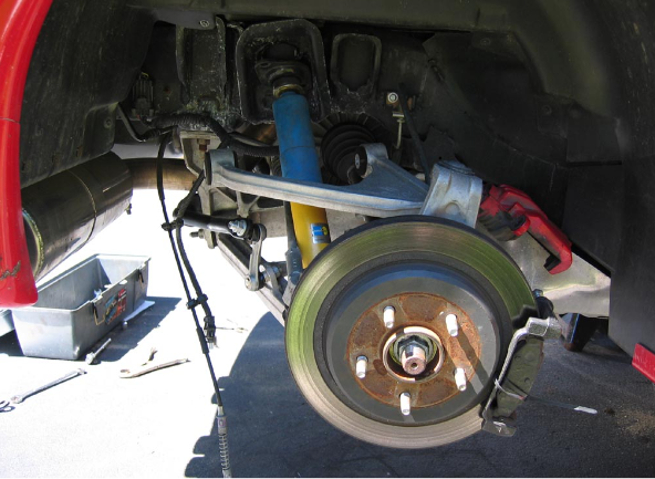
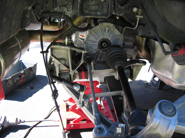
Pull the halfshaft out of the differential (you can use a prybar, or just do as I do and yank on the top of the spindle and it’ll pop right out). Disconnect the small 2 pin wiring harness right near the ebrake. Remove the ebrake cable from the back of the spindle. Pull the ebrake cable out of it’s bracket. This part is a little tricky – there’s 3 tabs to press in to be able to yank the cable. I used a small set of vice grips to hold 2 tabs in, then used a screwdriver to get the third.
Repeat all of this for the other side. When you’re done, it’ll look like this:
Step 4: Other rear-end work
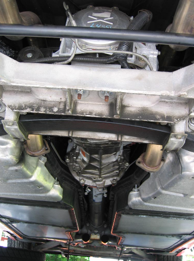
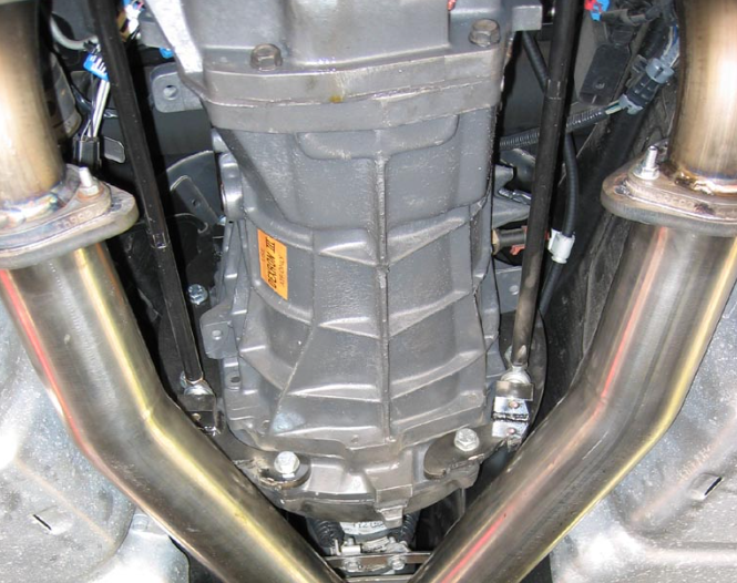
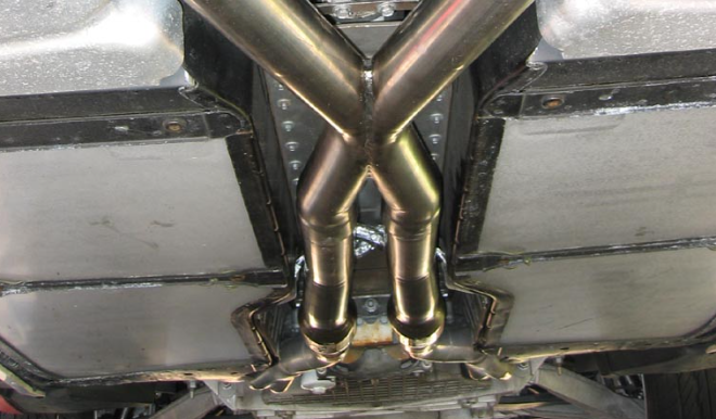
Undo the 2 15mm bolts that hold the over-axle pipes to the midpipe. You can wire/tie wrap through these holes onto a nearby bolt (there is a handy one on the side of the tunnel) to get these out of the way. If you are also swapping the mufflers, wait until you get the drivetrain out, they will be free and clear then. If you’re not swapping the mufflers, leave them like this, they will be out of the way. Pull the midpipe (I have headers, I just undid the clamps and yanked the midpipe out). There will be 2 13mm bolts hanging from springs near the back, don’t forget those. Watch the O2s sensors – pull the clips on the sides of the tunnel to prevent from stressing the wires. Undo 36 8mm bolts (hope you have air tools!) from the tunnel cover and remove it.
Now it’ll look like this:
Step 5: Preparation for lowering the drivetrain
Disconnect the intake tract from the TB to prevent from over stressing these parts when you lower the drivetrain in the next step. Remove the shifter from the car as well. This requires pulling the center console/HVAC and radio surround plastic piece. This large piece is held in with several T15 screws. There’s a couple of 10mm nuts holding a rubber pad over the shifter area. Remove them, then ensure that you are in neutral. There’s 4 more bolts holding the shifter in (10mm or 13mm). Remove the shifter.
Step 6: Lower the rear-end
I highly recommend you have at least 1 tranny jack for this next part. 2 is better – they are pretty cheap at Harborfreight.com. One under the rear suspension cradle and one under the tranny. Remove the 4 nuts holding the cradle to the car (21mm I believe). NO IMPACT TOOLS. Using impact tools can break the retaining rivet that prevents the large studs from rotating. If you do this, you will have to remove your carpet, and cut an access hole in the floorpan of your car. Not fun. Ask me how I know.
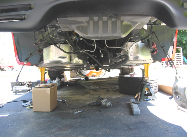
Slowly lower the rear end, watching for obstructions. The brake lines will pass in the space between the rear diff and the halfshafts that you have disconnected. Remove all wiring and brake line plastic push-pins that are attached to the rear cradle. Go slowly and KEEP looking for stuff to disconnect. There is a small wiring harness on top of the diff, and on the transmission for example. You can go pretty low with this:
I see a lot of people warning about hitting the firewall with the back of the engine. I don’t think this is much of a concern. I watched the back of the intake, and the plate over the driver’s fuel rail and they never came close to hitting. I stopped once the top of the rear diff was almost even with the bottom of the tub that hangs down in the back of the car.
Step 7: Disconnect the fitting leading the the slave cylinder
This next part is rather meticulous. First, disconnect the quick disconnect fitting leading to the slave (it’s a steel braided line with a big brass cylinder in the middle of it, towards the driver’s side of the car, coming out of the very end of the torque tube near the bellhousing). There’s several ways of doing this. What you need to do is push in the white (may be discolored grey depending on mileage) collar on that brass cylinder that is facing towards the front of the car. You can do this with a couple of screwdrivers if you have child size hands and a faultless patience. If you are like me, go to Advance Auto and pick up a Ford air conditioning + fuel line coupling disconnect tool (AmPro part # T70046). It’s basically 2 pieces of metal that are attached at the center (kinda like scissors). At the ends are 2 half circles. Use the 5/8″ ones and push in that white (in my case, gray) bushing on the end of the quick disconnect. Once it goes all the way in, it’ll ‘pop’ and the line will come free. This is really a gigantic hassle, but with the right tool that I mentioned, it works great. Save yourself the time now and get this part (or similar part).
Step 8: Torque tube preparation and removal
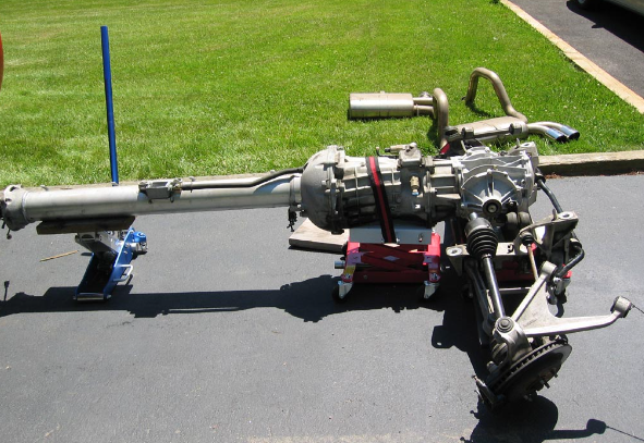
Remove the 13mm bolts at the end of the torque tube to the bellhousing. A good idea right now is to measure the height of your rear cradle/tranny and/or the jacks. This might make reinstallation easier later on. Put a jackstand or a small bottle jack underneath the oil pan so the engine won’t tilt when you remove the torque tube. Pull the torque tube (and attached tranny, diff, cradle) backwards until the shaft at the end of the tube is clear of the bellhousing. Remove the large wiring harness from the top of the torque tube once you can reach it. There’s a few connectors on the transmission to pull as well. Drop the tranny jacks all the way so that they will clear everything when you go to pull it out. WATCH the shifter base, it can catch the lines on the driver’s side of the tunnel. Just do it all slowly and keep looking at everything. Once it’s lowered all the way down, pull the assembly out from under the car. Ta da! If you want, you can leave the assembly where it was, but it can get in the way.
Step 9: Bellhousing preparation and removal
If you have headers that partially block the bellhousing, it’s time to pull them. It’s not necessary to completely remove them, just remove the 5 10mm bolts from each header flange and swing them out of the way (I used bungee cords to hold them out of the way). Pull the small bottom piece (inspection cover) of the bellhousing (a few 10mm and 13mm bolts).
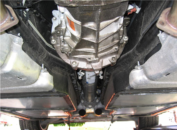
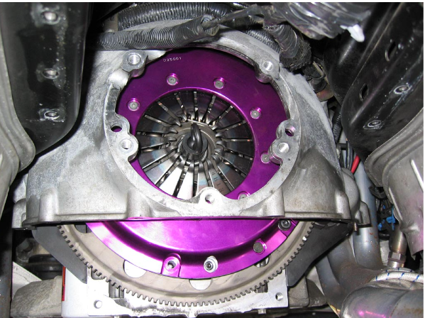
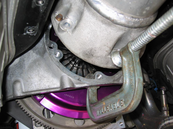
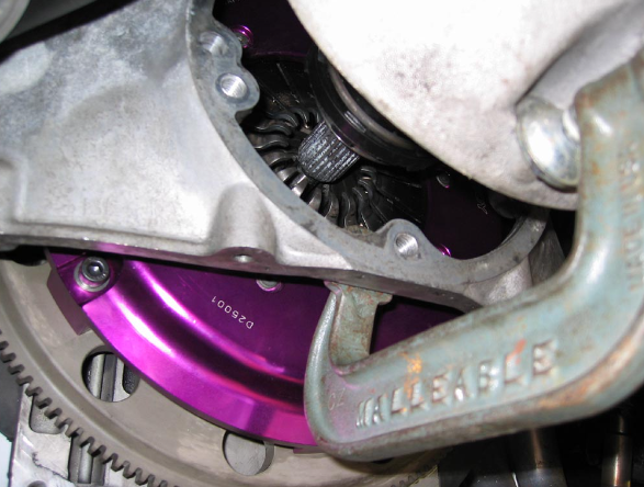
At this point, you can pull the 13mm bolts out of the bellhousing and remove it. I have heard that it is quite difficult to do this, however. I did the job without removing the bellhousing. However, you really should get a flywheel turner/locker. KD makes a nice one – part # KDT-2270. It will make your life bearable. It is very hard to turn the flywheel by hand to get all of the bolts out. Then later, you will have to tighten the pressure plate bolts in a star pattern which will really, really test your patience. The KD tool that I mentioned is only $30 or so.
This is where you should be at (provided you didn’t remove the bellhousing). This picture is cheating because the clutch is already swapped at this point.
Step 10: Pressure plate and clutch disc removal
Remove the 6 13mm pressure plate bolts (assuming you have a stock clutch). Be careful, the pressure plate AND the clutch disc will come out when you remove all the bolts. They are fairly heavy too. Remove the 6 15mm flywheel bolts and remove the flywheel. Sorry, didn’t take a pic of this part, but basically all you will see is the back of the engine and the crank.
Step 11: Pull the pilot bushing
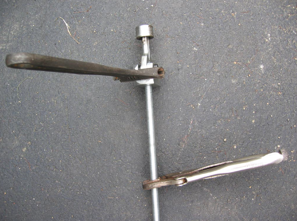
Now it’s time to pull the pilot bushing. This is a GIANT GIANT PAIN. You can buy or rent a bearing puller at autozone that is the right size. It has a screwdriver handle with a long shaft. There is a 2 prong jaw at the end of it, and a fairly large cylindrical weight on said shaft. If your luck is like mine, this tool will be useless as is. You stick the 2 jaws inside the pilot bearing (in the crank), tighten the jaws by rotating the handle, then throw the weight at the handle to yank the bushing out. Make sense? It’s great in theory, but unfortunately that short distance that you ‘throw’ the weight proves useless.
After doing it approximately 50 times, without the pilot bearing so much as budging, I went to home depot. 2′ of 1/2“ threaded rod, 2 nuts and 3 fender washers later, and I had my own tool. I put the jaw on the end of it, the 3 fender washers backed by 2 nuts at the other end, with the weight in the middle. Now you can throw the weight 2 feet. I ran into another problem at this point, the force was much greater but this just caused the jaws to slip out and not grab the pilot. That’s fine. Vice grips on the threaded rod, adjustable wrench on the head of the tool, and tighten that sucker till you can’t get it any tighter. Crappy pic of my tool:
After another bunch of whallops, interrupted only by re-tightening the jaws (when you turn the threaded rod, the jaws get tighter), it finally came out, completely destroyed:
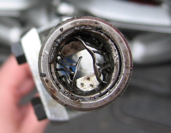
As you can see, the jaws ripped out the center of the bearing (all the little rollers came out) until it came to the outer (facing the rear of the car) lip, where it finally caught. I seriously spent a good 4 hours total on just the pilot bearing. Pray that yours comes right out with the simple bearing puller.
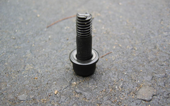
Step 12: New pilot bearing installation
Install the new pilot bearing with the flat side OUT. I have read conflicting reports on this one. All I know is that my factory pilot bearing had the flat side out, and the ‘bearing’ side facing the crank, so I put it back in that way. To install, find a socket that is about the same size as the outer diameter of the bearing. Lubricate well, and hammer that sucker into the crank. When this doesn’t work, grab progressively larger and larger hammers until that piece of crap is flush with the outside of the crank.
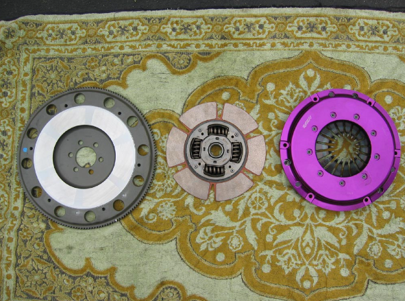
Grab your new clutch assembly. I used Exedy single disc, ooh pretty:
Step 13: Flywheel installation
Install the flywheel. 6 bolts, I recommend at least blue loctite. Tighten in a criss-cross pattern in 2 or 3 steps. I did 30, 50, then 74 ft/lbs. At this point, clean the crap out of the face of the flywheel with a clean rag and brake cleaner. It MUST be absolutely clean! While you’re at it, clean the face of the new pressure plate and both sides of the clutch disc.
Put the clutch disc in the pressure plate and put both pieces up against the flywheel. Attach with 6 bolts HAND TIGHT. Stick your alignment tool (or preferably, an old input shaft is even better) through the pressure plate, the clutch disc, and into the pilot bearing. Tighten the bolts in a criss-cross pattern with 2 or 3 steps (final is 50ft/lbs). This is the stock spec. If you have an Exedy like me, the FINAL torque spec on the PP bolts is 23ft/lbs! (flywheel is the same as stock). DO NOT TIGHTEN TO 50ft/lbs, you will end up with this (sigh):
When you’re done, the alignment tool should easily slide in and out. If it doesn’t, re-do it. I found that hand tightening the bolts, wiggling the alignment tool, then slowly tightening the bolts (give the tool a wiggle every once in a while to check the tension on it) works best.
If you’re replacing the slave, do it now. It’s on the end of the shaft that’s coming out of the torque tube. The throwout bearing is attached it via a big spring. To remove the bearing, push it in and rotate it counterclockwise until it pops out. Replace it if you desire (push in, turn clockwise until it stops). Replace slave if you desire, and/or add bleeder extension at this point (a wise decision if you do).
Step 14: Drivetrain reinstallation
Now it’s time to stick that drivetrain back in. This is really fun to do by yourself.
First, lower the transmission jacks all the way. Slide the whole thing under the car until the tip of the input shaft is just shy of the bellhousing opening. Remember we measured the height of the jacks earlier? Now you can put this to use. Raise the jacks slowly. You will have to alternate back and forth (it would help to have a friend here), as one jack cannot support the entire weight of the drivetrain (each one can only hold 450lbs), and it won’t lift very much if the other jack hasn’t been raised as well. I also broke out an old bottle jack to use at the end of the torque tube, to aid in lining up the input shaft with the clutch assembly. Put some lithium grease on the input shaft, some people have reported squeaks if you don’t. Plus, it will aid in re-assembly. Don’t douse it, you don’t want to get it on your clutch!
Once you’ve gotten the jacks to the correct height, and the input shaft looks lined up, start pulling (or have someone push) the driveline into place. This is a giant PITA to do yourself. First off, the drivetrain is very heavy, and trying to guide it slowly into place while lying under the car is quite uncomfortable, to say the least. Once you’ve got it close enough, you’re gonna need some help. You have to line up the splines correctly. There is no place to grab at the front (end of torque tube) so I used a c-clamp like so:
Crank the c-clamp down to draw the drivetrain into the clutch. I used a flywheel holding tool (this is immensely useful btw, I highly recommend one – wish I had a pic. It is universal and is made by SK tools). Try to bring the driveline together so that the input shaft goes through the clutch disc’s groves and into the pilot bearing. If you have my luck, you will have to back it off, turn the flywheel .00000000001mm, and try again, until it finally meshes (sigh).
You’ll know when you’ve got it. Keep pulling it closer and closer. As you are almost completed, make SURE that the drivetrain is angled DEAD on, and is ALSO level side to side (use a level on the rear swaybar if you’re unsure). This is important, because to get it all the way in, you use the bellhousing bolts to draw it the rest of the way. If the drivetrain is angled funny, you are going to crossthread the bolts in the bellhousing (which will really, really ruin your day). Trust me, I almost did it. Just go slow and keep looking at everything.
Step 15: Finishing touches
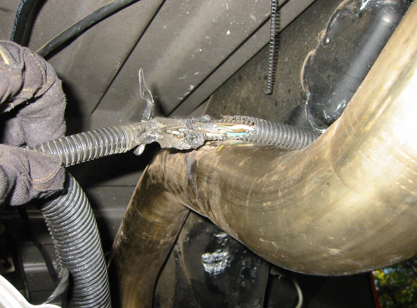
From here on, it’s pretty straightforward. Re-connect and re-tighten everything, and see if it works! Watch the wiring on top of the torque tube, it’s easy to pinch. Watch the wiring harness that goes near the rear mufflers, make sure you don’t rest them on the pipes, or they will burn. See the previous owner’s handiwork:
All done!
-Dope
The End! If you want to keep up to date with all the fresh Corvette news and maintain a pulse on the lifestyle and culture of this exciting, iconic brand, CorvSport has the fastest-growing Corvette community on our Facebook page, with over 173,000 followers (54,000 since January 2023!). Come join other hardcore enthusiasts and say hello, Douglas B.