
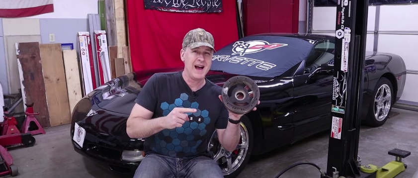
Welcome to the continuation of a new DIY series where CorvSport canvasses the internet for the best do-it-yourself guides. Let CorvSport be your digital encyclopedia and bring you the best guides and resources from our vast Corvette community. This series can also give an enthusiast contemplating a DIY project the clarity needed to realize they should hire an expert.
One of the most common issues to address on the fifth-generation Corvette is the wobbly harmonic balancer (aka crank pulley or damper–the issue also carries over to the C6). Leave it up to the GM engineers to design a two-piece balancer connected by rubber, which was prone to wobbling as the rubber degraded. Most enthusiasts will agree this degradation is a factor of time and not just miles. I can confirm this as the harmonic balancer on my 2000 FRC with only 35,000 miles was wobbling, but the integrity of the balancer was still intact. It’s important to note that, contrary to popular opinion, a wobbly balancer does not guarantee a failure. So, given that dynamic, here are some initial tips.
Do I need to replace and upgrade? Tips for monitoring:
1) When do I need to replace and upgrade with an aftermarket balancer? If your balancer looks like this, stop driving immediately. Notice how the two sections have separated.
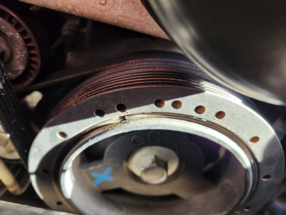
2) Mark and monitor your balancer for slipping. This is the balancer from my 2000 FRC with 35,000 miles. While it had a distinct wobble, there was no slippage, and the integrity of the rubber looked good. Use a Sharpie-type pen to make your mark across both pieces.
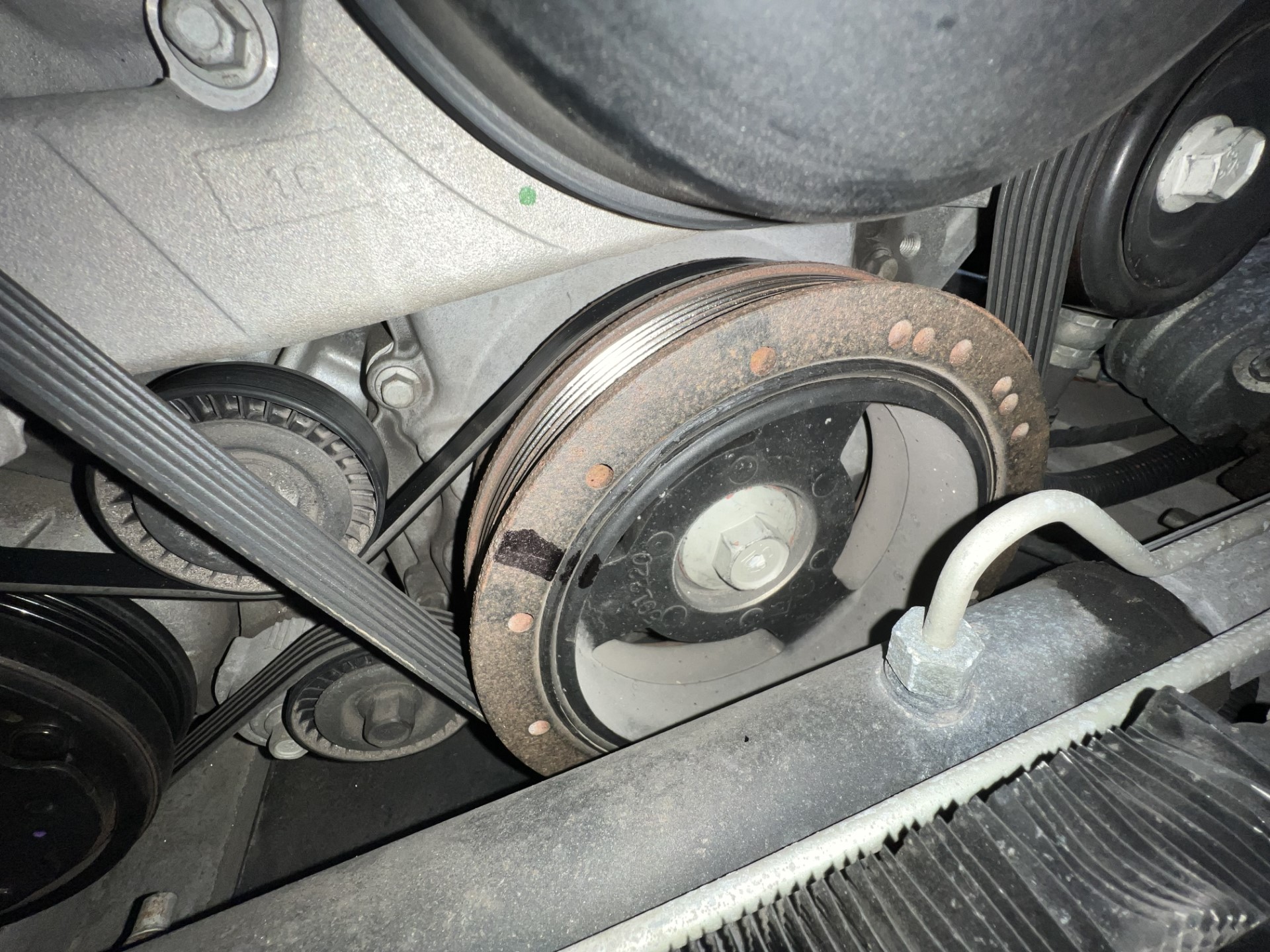
3) For reference, here is what the typical wobble looks like. Along with the wobble, you may notice some chirping. Many enthusiasts err on the side of caution and replace the balancer due to a wobble only, but as I’ve noted, I’m in the camp that monitoring the integrity of the rubber and slippage are the first steps for assessing whether a replacement is necessary.
CorvSport Complexity Guide
- Difficulty: 9.9 (10 most difficult)
- Patience Needed: 10
- Level of Specialty Tools Required: 9
- Is a Helper Recommended? Yes
Today’s guide comes from Corvette Forum member “scottunger” and is the best and most comprehensive guide I could find on the internet. It is very detailed but, unfortunately, did not include any accompanying pictures. I’ve included two popular YouTube videos below so you can augment the written instructions with some visuals. This curated C5 harmonic balancer replacement is fully credited to “scottunger” and is being presented to our CorvSport community in an unedited format.
How To Replace The Harmonic Balancer On Your C5
Opening words from scottunger:
“A few weeks ago, I completed the harmonic balancer replacement (aka crank pulley, damper) on my 2000 C5. Leading up to the project, I did weeks, if not months of reading, including this forum and several different websites. Do this. Don’t do this. Make sure you do this. God forbid, don’t do that.
Bottom line, different things work for different people. Some don’t have a 2-post lift in their garage and had to do the project crawling around on the floor while utilizing jack stands. Fortunately, I recently had a lift installed in my shop and it made this a much less back breaking exercise. So, what I wanted to do was share my experience and maybe give you a one stop place for this DYI project so you don’t have to do the weeks of research I did and yes – it is a DYI job.
If you’ve ever turned a wrench, you can do this. For those of you who don’t have a lift in your shop, I’ll try to offer some suggestions as I go along, however I’m not going to include “so and so said do this”. This is specifically a write up on how I successfully completed this project. I don’t have pictures, but the descriptions I offer are pretty comprehensive. Again, these are suggestions based on how I did this project…If you have all the parts/tools listed here, you can knock this out in a weekend. Good Luck!”
Step 1
Parts List – these are suggested parts. You can get whatever you want. This is what I went with based on research for the best way to go:
– DAYCO Harmonic Balancer Part number PB1117N premium
– ARP 2342503 Stud Kit (includes the ARP bolt lubricator)
– National 100470 Oil Seal (don’t HAVE to do this, but you’re in there. Might as well.)
– Power steering fluid (don’t need much, so if you have half a quart around the garage, that will do)
Step 2
Tools Needed (absolute needs)
– Flywheel flexplate holding tool – I found one on eBay for $25. Don’t pay $115 for the name brand one. You don’t need it. Search eBay for the “corvette c5 flywheel flexplate holding tool” and plan for a week delivery.
– A wide ranging set of metric wrenches, sockets and ratchets (both 3/8” and ½” drive)
– Measuring caliper, digital is easiest, but make sure it has the little nub that comes out of the bottom of it
– Short crow bar
– Long crow bar
– 6 lb sledge hammer
– Torx 20 bit
– Set of Alan wrenches
– ½” Drive Breaker Bar
– 4 feet of pipe that has a wide enough opening to accept the ½” breaker bar
– WD40
– You’ll need a tool to press the new balancer on the crank shaft. I’ll explain mine in step 25.
Step 3
Tools to borrow from AutoZone – borrow these tools, literally. You pay for the cost of the tool up front and they refund the whole thing to you when you return them. So, it’s free and you can keep them for up to 90 days. Also, it doesn’t have to be AutoZone. Most parts stores “rent” tools.
– Torque wrench (that can be set to from 33 to 240 ft-lbs). This may require two separate torque wrenches.
– Chrysler Harmonic Balancer Puller
Step 4
Other Suggested Things to Have On Hand
– 18mm Flare nut wrench
– 2 or 3 blocks of wood (if you’re working on jack stands)
– Some kind of adjustable stand that is a minimum of 3 feet tall (if you’re working on a lift)
– Drain pan
– Rags/Towels
– I have an air compressor and a 3/8” drive air ratchet which made a few things easier, but not necessary
– A ¾” inch self-tapping screw
– Some kind of drill, cordless or otherwise
Step 5
Pop your hood and do two things:
a. Disconnect the battery.
b. Remove the main serpentine belt. This is easily accomplished by removing the idler pulley (passenger side of the car, highest pulley in the engine bay) using a ½” drive ratchet with a 15 mm socket. Once you have the pulley off, the belt will fall off. Remove the belt completely from the car and set it aside. Replace the idler pulley and torque to 37 ft-lbs.
Step 6
Break loose the lug nuts on your front tires while the car is on the ground. Get your car in the air. If you have a lift, all the better. If you have to use jack stands, get the car up as high as you can to make this job easier on you. In the end, you can’t place the jack stands on the front cradle. You’ll have to find somewhere else to place them. Remove the front tires.
Step 7
Remove the front sway bar. There are 4 bolts (2 – 15 mm on each bracket). Mark the brackets as they fall off for proper replacement. Then you’ll need to remove the ends of the sway bar from the A-arms. This will take a combination of an 18 mm wrench and the Torx 20 bit. I put the Torx bit in a ratchet with a ¼” socket and a long extension. You’ll need to hold the Torx screw while wrenching the nut loose, otherwise the nut will just spin. Do this on both ends of the sway bar. I put the sway bar bracket bolts in a Solo cup and marked the cup, but separate them however you need to so you don’t lose them. I put the nuts loosely back on the bolts on the A-arm not to lose them.
Step 8
Detach the tie rod ends from the spindles on either side of the car. You’ll do this in the same fashion as the end of the sway bar, using an Alan wrench in place of the Torx bit. As you loosen the nut, just prior to it coming off (leaving at least 3 threads connected), smack the top of the nut with your wrench. This will easily pop the tie rod end out of the connector on the spindle. Remove the nut the rest of the way, then replace the nut onto the threads after the tie rod end is disconnected so as not to lose it.
Step 9
On the front of the front cradle, there are power steering cooling lines held on with 2 – 10 mm bolts. Remove those, pull the lines slightly forward, then replace the bolts in the holes as to not lose them. You can let the power steering lines dangle for now.
Step 10
Attached to the driver’s side of those power steering cooling lines is the Magnasteer connector. Detach the connector from the power steering line and unplug the connector. You can let that dangle, but it will come out as you pull the rack out of the car.
Step 11
On the driver’s side of the vehicle now, you’re going to do 2 things:
a. Remove the two power steering lines that go into the steering box. Both are 18 mm fittings. **Have patience with this. You don’t want to round off these fittings. Big headache if you do**. Take care not to nick the flared ends the best you can. You can let the one attached to the power steering cooling lines on the front of the cradle dangle. I slid the other flat under the steering box to get it out of the way.
b. Remove the 13 mm bolt that holds the steering column to the steering box. You may need to turn the steering wheel for good access to the bolt head. Solo cup the bolt.
Step 12
Return to the front of the car and remove the 2 – 18 mm bolts holding the steering rack to the front cradle. You’ll have to use a wrench on the nut on the back and a ratchet on the front. Solo cup the two bolts separately so you know which goes on either side of the car for later.
Step 13
On the driver’s side of the cradle are 4 – 13 mm bolts holding the bracket for the EBTCM. Remove those 4 bolts and Solo cup them for now. Now you need to lower the front cradle. You don’t remove it. Using a ½” drive ratchet with a 21 mm socket, you will need to go around to the 4 vertical bolts holding the cradle and loosen them a little at a time, so as to slowly bring the cradle down. This will take some effort. In the end, you need to 3 or 4 threads left engaged on all 4 bolts in order to have enough room to slide the steering rack out of the car. Once you have the bolts loose, you will need to use your small sized crow bar and wedge it between the cradle and the chassis. This will likely require smacking it into place with a hammer or sledge so as to keep the cradle held as far down as possible.
Step 14
At this point, you’re ready to remove the steering rack:
a. From the passenger’s side of the car, you’ll need to use your longer crow bar to get the steering rack’s passenger side fitting out of its bracket. I was able to get the crow bar under the fitting and pry it out of the bracket to some degree, but then I had to smack the end of the crow bar towards the driver’s side while placing it against the side of the fitting. You’re going to have to do something of the sort because the steering rack won’t come out by hand. It’ll have to be forced out in some fashion.
b. Place your drain pan under the left side of the car to catch power steering fluid. Keep some towels handy, too.
c. Once the rack is loose from the passenger’s side bracket and you start to pull the rack from the driver’s side of the car, be patient. It will come out. As you start, reach up and knock the steering column loose from the nub on the steering box. Once the steering column is loose, you may need to twist the rack in place to get past certain things. Also, you will likely need to lift the EBTCM bracket as high as you can out of the way from the front of the car. Suggestion: you can push the EBTCM bracket pretty far up out of the way and keep it up there by pushing it high enough to get the 2 bottom bolt holes on the bracket lined up with the 2 upper bolt holes on the cradle and use two of the bracket bolts to secure it up there. This will come in handy later, too, so just leave it up there.
d. Keep in mind the Magnasteer connection that is connected to the steering box. It will come out with the rack, so make sure not to damage it.
e. Finally, take care to not pull on the tie rod ends to get the rack out. This will cause the nub in the steering box to turn and while not the end of the world, it’ll make for an irritation later. It takes some effort to pull the tie rod end enough to turn that nub, but just don’t do it.
Step 15
Once the steering rack is out of the car, check it over for wear and tear. One of the boots on mine had some rub marks. Replace parts as necessary and be sure to take care to not let anything get into the power steering holes.
Step 16
At this point, you are going to need to secure the flywheel to get the bolt off the crank pulley. To do this, you need to remove the starter and to have access to the starter, you will need to lower the exhaust pipes from the exhaust manifolds (3 – 15 mm nuts on each manifold and 2 – 15 mm bolts just in front of the catalytic converters). There are also 2 – 13 mm bolts about 2/3 of the way towards the rear of the car (they have springs attached to them) that you might need to remove also, in order to get the exhaust pipes lowered. If you’re working on jack stands, have a couple blocks of wood handy. You may need them to keep the exhaust pipes elevated to some point because the O2 sensors will still be connected and you can only lower the exhaust so far before damaging those sensors or the connections. If you’re on a lift, you can use some kind of stand to hold up the exhaust.
Step 17
Once the exhaust is detached from the manifolds, you’ll have access to the starter. If you didn’t disconnect the starter at the beginning of this, do it now! On the front of the starter is a 15 mm nut holding 3 wires to the starter. Take note (or a picture) of the positioning of the wires before you loosen the nut. You will need to return the wires to the same position when you replace them. Loosen the nut, remove the wires and replace the nut back to the stud on the front of the starter, so as to not lose it.
Step 18
With a 3/8” drive ratchet, a long extension and a 13 mm socket, remove the two bolts holding the starter to the engine block. They are actually in a vertical position, one on either side of the starter. Once they’re removed, the starter can be pulled out of the bellhousing towards the front of the car. There is still one wire connected to the starter at this point. You don’t need to remove it. Just shimmy the starter towards the passenger side of the car to give yourself enough clearance to access the hole where the starter was.
Step 19
You can now connect the flexplate flywheel holding tool. I ended up using one of the longer starter bolts instead of both of the bolts that came with the tool. This is tricky, so be patient. Once the flywheel holding tool is in place, you can now remove the crank pulley bolt. If you’re working on jack stands, you’ll have to do this from the top side of the car; on a lift, using your ½” drive breaker bar and a 24 mm socket, place the socket on the bolt and then slide the 4 feet of pipe onto the breaker bar (Torque is your friend) and loosen the bolt. With that much pipe, the bolt should come off like butter (nothing short of this worked, including a commercial impact gun).
Step 20
At this point, my suggestion is to measure the distance from the end of the crank to the outside of the pulley bore using your measuring caliper. This depth measurement should be 2.40-4.88 mm. You will want to return the crank to this position when you press it on.
Step 21
You will need to remove the A/C belt that loops the A/C compressor and the crank pulley. Using a 15 mm wrench on the lower of the two tensioner pulleys, you can remove this belt and set it aside.
Step 22
You can pull the crank pulley off the crank. I used the Chrysler Harmonic Balancer puller after trying several different methods. However, the tool you rent from AutoZone may or may not have the proper length rod to slide into the end of the crankshaft for proper removal. After many hours of consideration, I ended up using a short and long ¼” ratchet extension connected together, sliding the narrow end in the tool and the female end down the snout of the crankshaft. This worked like a dream. Still takes a little muscle, and while slow going, it’ll come off.
Step 23
Once the balancer is removed, this is when you replace the front oil seal, if you’ve decided to do this. If you aren’t doing this, skip to step 25. Take your 3/4” self-tapping screw and screw into the 8 o’clock position of the oil seal. Leave enough head that you can get your crow bar onto it and pry the seal out of its position. Two important things here:
a. Don’t use the crankshaft as a fulcrum. You don’t want to mar the end of the crankshaft.
b. Be careful not to nick the edge of the where the seal goes into the timing cover. Just use some common sense here and be careful when prying that seal out. This works really well and just grabbing the thing with pliers doesn’t work.
Step 24
Replace with the new seal. Get it centered and I just used a medium size socket and a hammer to get it to seat properly, smacking it all the way around the clock (noon to noon). Be sure the edge of the seal is flush with the timing cover.
Step 25
Now to press the new pulley on the crank. Note: everything I’m working with here is stock. If you have an aftermarket pulley already on the car, you may need to make sure you have any weights on the pulley properly clocked on the crank. Also, if your crank is keyed (which the stock isn’t), make sure you have the keyhole lined up. Here’s what I used to press my pulley onto the crankshaft: I went to Fastenal and purchased a 6 inch 16M x 2.0 bolt that is 10.9 Grade, along with about a dozen washers that fit the bolt, between 1 3/4 and 2 inches in diameter (so it fits into the pulley bore). DO NOT use anything less than 10.9 Grade. The bolt threads have to be strong enough to ensure you don’t strip out the threads in the crankshaft. There are several pulley pressing tools out there, but I couldn’t find one that works. This way took a while because I had to order the bolts, but it worked like a gem once I received them. Press the pulley onto the crankshaft, taking care that you go slowly for the last half of the process. Once you start getting close to the end, you will need to remove the tool several times so that you can measure that 2.40-4.88 mm distance between the end of the crank and the outside of the pulley bore.
Step 26
Once the pulley is in place, lube your ARP bolt according to ARP instructions and torque to 240 ft-lbs. This is going to take some effort. If you’re working on jack stands, you’ll likely have to do this from the top side.
Step 27
Now put everything back together.
Step 28
Replace the A/C belt.
Step 29
Remove the flexplate flywheel holding tool.
Step 30
Replace the starter, torqueing both bolts to 37 ft-lbs.
Step 31
Reconnect starter wires being sure to clock the wires the way they were. Tighten the nut, but don’t overtighten.
Step 32
Reconnect the exhaust system.
Step 33
Reinstall the main serpentine belt using the idler pulley by pushing it all the way to the driver’s side of the car. The routing of the belt can be found in your owner’s manual on page 6-76.
Step 34
Reinstall the steering rack. Again, this will take some finesse and patience. Don’t push or pull on the tie rod ends. Once you have it worked into place, you will likely have a difficult time wedging the passenger’s side bushing into the bracket. I ended up using my long crow bar and prying it into place, using one of the pulleys behind the rack as a fulcrum. Not ideal, but I didn’t see any other way to get it into place. That thing is a bugger. Try twisting the rack back and forth by hand to get the rubber grommets into place between the ears of the bracket. Once you have the rack in place, insert the passenger side bolt and nut but don’t tighten it down just yet.
Step 35
Drop the EBTCM bracket back into place. Reinsert the driver’s side rack bolt but don’t tighten down just yet. You can secure the 4 EBTCM bracket bolts to 37 ft-lbs.
Step 36
Raise the cradle back into its original position. The 4-21-mm nuts get tightened to 80 ft-lbs.
Step 37
Reconnect the steering column. If you didn’t pull on the tie rod ends, you should have no problem with alignment. Also, the steering column only attaches one way (the nob on the steering box is flat on one side), so it should slip right back on. Tighten the bolt manually, but crank it down good. (No torque specs)
Step 38
You can now torque the steering rack bolts to 74 ft-lbs.
Step 39
Reconnect the power steering lines back into the steering box. This needs a lot of patience. My suggestion is to get them lined up the best you can with the flange down in the proper hole, push the fitting into the hole and spin it by hand counter-clockwise while applying a little pressure. You’ll feel the fitting “click” and when you feel that, you know the fitting is seated properly so as not to cause cross-threading. You do not want to cross thread these, so make sure you have those fitting properly seated before you tighten them down. The line that runs to the front of the car goes in the driver’s side-most hole in the steering box, but you’ll have to do the other one first. Tighten snugly, but don’t overtighten. Your 18 mm flare nut wrench comes in handy here.
Step 40
Reinstall the power steering cooling lines on the front of the cradle. Tighten, but don’t overtighten.
Step 41
Reattach and reconnect the EBTCM connector on the power steering cooling line.
Step 42
Tie rod ends are next. Start on the driver’s side and connect the tie rod end loosely. Position the wheel spindle so the wheels would be straight and check your steering wheel. It should be straight. If it’s not, you’re going to have to make sure corrections, but it should be fine.
Step 43
You can now tighten the tie rod end. Again, you’ll need to use the Alan wrench and a 18 mm wrench to start out. Once you have a couple threads of the bolt through the nut, you can torque them to 33 ft-lbs.
Step 44
Reattach the sway bar, being careful to center it. Torque the bolts on the front cradle to 43 ft-lbs and the ends on the A-arm to 53 ft-lbs. Again, you’ll need to use the Torx bit to get the nuts started on the A-arm.
Step 45
Remount the wheels. Torque to necessary specs. I use 100 ft-lbs.
Step 46
Lower the car and reconnect the battery.
Step 47
You should be ready to crank the car up. You are going to have to refill the power steering reservoir and bleed the air out of the system. Pour some power steering fluid into the reservoir before you start the car (up to the cold line). Once you crank up the car, turn the wheel stop to stop a couple of times and then refill the reservoir back to the cold line. This should be enough to bleed the system but you will want to check it again soon.
Step 48
How’s your car running? Should be running like a champ and your wobble will be gone. You should be checking for thrown codes, power steering fluid leaks or anything out of sorts. If all seems well, take her for a test drive.
Step 49
After 40-50 miles, you should come back and reapply torque to all bolts to ensure proper tightening.
Step 50
Enjoy your new crank pulley and no more wobbling!
The End! If you want to keep up to date with all the fresh Corvette news and maintain a pulse on the lifestyle and culture of this exciting, iconic brand, CorvSport has the fastest-growing Corvette community on our Facebook page, with over 173,000 followers (54,000 since January 2023!). Come join other hardcore enthusiasts and say hello, Douglas B.
Additional Resources
1) Popular YouTuber Toys4Life C5, whose video has 44,000+ views and 1900 likes.
2) Toys4Life C5 offers another comprehensive video with over 15,000 views and 664 likes.