NOTICE: While Corvsport.com has made every effort to ensure that the instruction provided on this site is both complete and accurate, it is presented here for REFERENCE ONLY. All vehicle maintenance and repairs should only be performed by a qualified technician or mechanic and should not be attempted without the proper tools and/or experience. Improperly performed vehicle repair can result in damage, injury, and even death. User discretion is advised.
GENERAL ELECTRICAL SYSTEM DIAGNOSIS
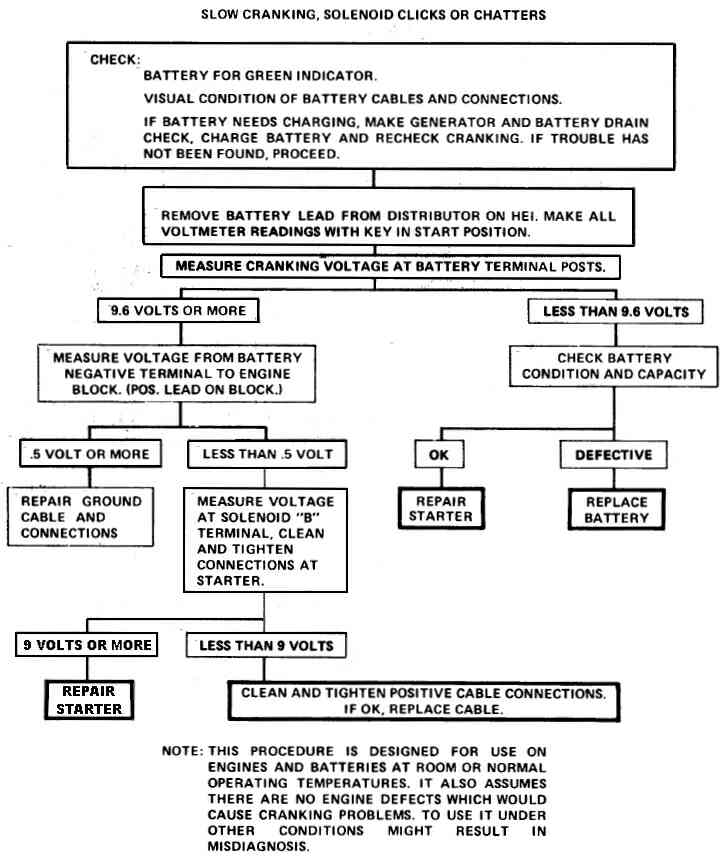
The engine electrical system diagnosis includes the battery, the starter, and the generator/alternator (and related wiring.) The following diagnosis charts will aid in troubleshooting system faults. When a fault is traced to a particular component, refer to the corresponding system repairs as defined on this page. Please utilize the links at the top of the page to find service instructions for each system.
BATTERY
A sealed battery is standard on all Corvettes. There are no vent plugs in the cover. The battery is completely sealed, except for two small vent holes in the side. These vent holes allow the small amount of gas produced in the battery to escape. The battery has the following advantages over conventional batteries:
No water addition for the life of the battery.
Overcharge protection. If too high a level voltage is applied to the battery, it will not accept as much current as a conventional battery. In a conventional battery, the excess voltage will still try to charge the battery leading to gassing, which causes liquid loss.
Not as liable to self-discharge as compared to a conventional battery. This is particularly important when a battery is left standing for long periods of time.
More power available in a lighter and smaller case.
The battery has three major functions in the electrical system:
It is a source of electrical energy for cranking the engine.
It acts as a voltage stabilizer for the electrical system.
It can, for a limited time, provide energy when the electrical load used exceeds the output of the generator/alternator.
COMMON CAUSES OF FAILURE
The battery is not designed to last indefinitely. However, with proper care, it will provide many years of service. If the battery tests good but fails to perform satisfactorily in service for no apparent reason, the following are some of the more important factors that may point to the cause of trouble:
Accessories are left on overnight. This could include leaving a cell phone charger (or similar device) plugged into the accessories outlet.
Slow average driving speeds for short periods.
the vehicle electrical load is more than the generator output particularly with the addition of after market equipment (such as stereo amplifiers, extra speakers, etc.)
Defects in the charging system such as electrical shorts, slipping fan belt, faulty generator or voltage regulator.
Battery abuse, including failure to keep the battery cable terminals clean and tight or loose battery hold down.
Mechanical problems in the electrical system such as shorted or pinched wires.
Freezing conditions, although the freezing point of electrolyte depends on it’s specific gravity. Since freezing may ruin a battery, it should be protected against freezing by keeping it in a charged condition.
BUILT-IN HYDROMETER
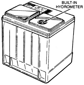
The sealed battery has a built-in temperature compensated hydrometer in the top of the battery. This hydrometer is to be used with the following diagnostic procedure. When observing the hydrometer, make sure that the battery has a clean top. A light my be needed in some poorly lit areas.
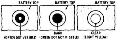
Under normal operation, two indications can be seen:
GREEN DOT VISIBLE: Any green appearance is interpreted as a “green dot” and the battery is ready for testing.
DARK; GREEN DOT NOT VISIBLE: If there is a cranking complaint, the battery should be tested. The charging and electrical systems should also be checked at this time.
Occasionally, a third condition may appear:
CLEAR OR LIGHT YELLOW: This means the fluid level is below the bottom of the hydrometer. This may have been caused by excessive or prolonged charging, a broken battery case, excessive tipping or normal battery wearout. When finding a battery in this condition, it may indicate high charging voltage caused by a faulty charging system and therefore, the charging and electrical system may need to be checked. If a cranking complaint exists and is caused by the battery, it should be replaced.
DIAGNOSIS
The following procedure should be used for testing batteries:
1.) VISUAL INSPECTION
Check for obvious damage, such as cracked or broken case or cover, that could permit loss of electrolyte. If obvious damage is noted, replace the battery. Determine cause of damage and correct as needed. If not, proceed to step 2.
2.) HYDROMETER CHECK
If GREEN DOT VISIBLE, proceed to step 3.
if DARK; GREEN DOT NOT VISIBLE, then charge the battery and proceed to step 3.
3.) LOAD TEST
NOTE: Load testing may require the use of battery side terminal adapters to insure good connections.
Connect a voltmeter and a battery load tester across the battery terminals.
Apply 300 ampere load for 15 seconds to remove surface charge from the battery. Remove load.
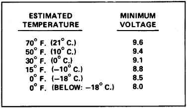
Wait 15 seconds to let battery recover and apply specified load from load test chart (see below.) Read voltage after 15 seconds then remove load.
If voltage does not drop below the minimum voltage listed (see below), the battery is good and should be returned to service. Temperature of the battery will change the minimum voltage to pass the load test. When performing this step, estimate the temperature that the battery has been exposed to for the last several hours.
BATTERY REPLACEMENT
Disconnect Negative battery cable.
Disconnect Positive battery cable.
Remove battery hold down clamp.
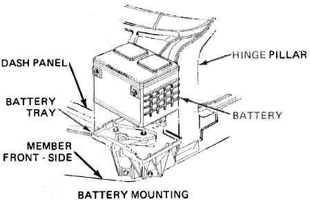
Follow “Fender Reposition” graphic (below) for battery removal.
Join 45,000+ Corvette Owners Who Read Our Newsletter
Our newsletter delivers all the Vette news, rumors, deals and events directly to you each week
Members only$35 / year
Keep going. This is where it gets good.
CorvSport Membership is for people who'd rather spend an hour inside one engine option than skim ten headlines. The rest of this story — and every other one like it — is a few seconds away.
Every members-only story
Deep history, market reports, buyer's guides, and the full archive back to 2010.
No ads. None.
The whole site reads like a magazine, on every device.
Every model year, 1953 to today
Production numbers, VINs, RPO codes, colors, options — one page per year.
30% off the shop
Every CorvSport shirt and piece of merch, all year.